.............CFB opamp .............. discrete CFB amplifier, ..........the CFB amplifier
.......CFB power amps are older than the VFB counterparts. The very first transistorized power amps,...........had an input stage comprising only one transistor and the feedback was applied to the emitter.......
..CFB = Complementary FoldBack = Sziklai
CFA = Current Feedback Amplifier
Hi,
it must depend on the context of the sentence, but when I think my readers may be confused, I will type out the full word/s first and then add, in parentheses, the acronym for later use in the text.
In this discussion we were all talking about feedback and I thought all the readers would realise from the thread context that I was not referring to Sziklai
.....
I haven't simmed it but I did build a variant of it a long long time ago. Made it fully bridged and used an INA103 as the input opamp. Sounded awesome but never got around to stabilising the bias currents - I changed the output stage to multiple paralleled logic-level MOSFETs for high gm.
I build this amp about 8 Years ago - and i found the same problem and solution as Abraxalito - i assume that the source of bias problems was that the prototype was running on ordinary MOS-FETs, and the Toshiba IGBTs was only theoretical example for the technical article (becuse it cant work - the thermal coefficient for IGBTS is double so high that the Vbe multiplier from this schematic).
I change the IGBTs for 2xIRF540 + 2xIRF9540 + (low ohm source reistor for each,and 200ohm gate resistor for each) - and afther that , the bias was very stable ! No problems with thermal runaways and overheating IGBTs.
Next step was to change the SSM2131 for BUF634 in narrow BW mode.
The sound was very fast, full of air, but a bit to thin - i replaced it later by DIY Aleph3.
I'm simulating the Alexander amp myself now, using a BJT output state
Oscillation hasn't been a problem, but not many opamp models simulate power rail behaviour ! For example, the OPA2134 I plan to use does not. LT1001 model in LTSPICE does however. I am using Fairchild's outputs and drivers.
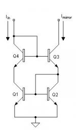
The Arcam DiVA A85 and Arcam FMJ P7 are also variants of the Alexander amp, though they use a different current mirror scheme.
Oscillation hasn't been a problem, but not many opamp models simulate power rail behaviour ! For example, the OPA2134 I plan to use does not. LT1001 model in LTSPICE does however. I am using Fairchild's outputs and drivers.
The Arcam DiVA A85 and Arcam FMJ P7 are also variants of the Alexander amp, though they use a different current mirror scheme.
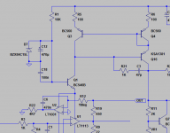
In attachment You will find zip with .CIR file for MicroCap6.0 spice simulation.
It was the last variation of my M.Alexander CFB amp based on:
- OPA604AP - but later replaced by BUF634 in narrow band mode (both ae superior to the SSM)
- output stage on IRF Mosfets - (no changes in the VBE multiplier are needed, i Run it on only 30-40mA of bias on 67V supply rails, and the stablity of bias current was OK)
An externally hosted image should be here but it was not working when we last tested it.
Attachments
Last edited:
I'm simulating the Alexander amp myself now, using a BJT output state
Oscillation hasn't been a problem, but not many opamp models simulate power rail behaviour ! For example, the OPA2134 I plan to use does not. LT1001 model in LTSPICE does however. I am using Fairchild's outputs and drivers.
The Arcam DiVA A85 and Arcam FMJ P7 are also variants of the Alexander amp, though they use a different current mirror scheme.
This is the main issue.
There are some commercial and diy power amplifier with an operational amplifier as front end, but naturally the signal pad comes from the output of the OP-AMP.
But there are a second kind of signal flow.
In this case the normal output from OP-AMP goes to GND (resistor between 100R and 1K) and the signal out will fetch from the positive and negative PIN from OP-Amp for the voltage supply.
This kind of signal flow is for me very special and not mentioned here:
I can't find the associated design rules for that kind of signal flow. I assume, this haven't to do with the kind of global NFB and start therefore this thread:Having spent some time in analysis by the Alexander's amp structure, I concluded that it was quite conventional. What I did not know and confirmed my way of thinking is that Peter Baxandall has said the same much prior to me.
His comments on current feedback can be found in Talbot-Smith's "Audio Engineer Reference Book' :
"The term 'current feedback amplifier' has appeared in op-amp manufacturer's literature (Ogden, 1992) since about 1985 and also in audio power amplifier context (Alexander 1990). It is implied that a new basic principle is involved, but really it is an old one in disguise [...]"
http://www.diyaudio.com/forums/soli...pamp-signal-pad-power-supply-rail-naming.html
Last edited:
in this case this thread is of interest
http://www.diyaudio.com/forums/solid-state/108791-alexander-amp-current-feedback-opamps.html
http://www.diyaudio.com/forums/solid-state/108791-alexander-amp-current-feedback-opamps.html
- Status
- Not open for further replies.
- Home
- Amplifiers
- Solid State
- Alexander amp