Anyone simulated the current feedback amplifier by Mark Alexander?
I tried just for the heck of it but it seems to oscillate with an frequency of 50-60MHz, with a Vpp with about 500mV. Anyone else tried to simulate this amp? Can't really figure out where the problem lies.
Don't really know how to add pictures.
AN-211:
http://www.google.se/url?sa=t&sourc...Wzr8XDtg3mhGLA7cQ&sig2=LflaMAhr9s8ex8BlsQE2Lg
Last edited:
Interesting. Did you figure out why?
EDIT:
I mean, looking at the loopgain it seems that is far from unstable.
Also I tried to implement a CMCL but it did not seem to do any good really, maybe I did it wrong, gave it one hour or so... 🙂
EDIT:
I mean, looking at the loopgain it seems that is far from unstable.
Also I tried to implement a CMCL but it did not seem to do any good really, maybe I did it wrong, gave it one hour or so... 🙂
Last edited:
I never did figure out why. I built it on a breadboard and chalked it up to that, figuring to get it running I'd have to do a board. A decade passed and then some. Here we are. Let me know if you want a couple old Toshiba IGBTs.
Thanks, but I think I'll let it go, atleast for now.
I think the simplicity of the amp is very interesting, but i'll think I'll dig into descrete input stages. It seems there is plenty of them around to learn a couple of things from.
My opinion is that even though Mr. Alexanders AES article is fairly old, there are'nt many of this amps with OPAMPS as input buffers (atleast I have not seen many), so maybe this is a fairly common flaw with this type of amp. Would still be nice to figure out why it behaves this way. 🙂
Thanks for your fast reply, your answer made do something else with my sunday, instead of thinking of what I did wrong in my testbench.
/Icko
It is not unusual CFA oscillate.
Especially if you try to run the whole amp from same Voltage supply.
A good way to prevent oscillation
is to let the Output stage have a separate supply.
And the input+vas stages should have a regulated voltage supply.
This will make the amp have a good chance to be stable.
Especially if you try to run the whole amp from same Voltage supply.
A good way to prevent oscillation
is to let the Output stage have a separate supply.
And the input+vas stages should have a regulated voltage supply.
This will make the amp have a good chance to be stable.
Tackar Lineup.
I shall have that in mind when stuff starts to get practical. Right now it seems that I am going to build a cfp amp. Atleast doing simulations of them is very enjoyable. 🙂
But, it was a pretty simple testbench I hade were the supply rails were ideal so I don't think that was the case this time.
/Icko
Okay.
Then the compensation is different for CF Amps.
The usual compensation small caps should be placed elsewhere.
But I never have learned and I am not sure how to put capacitors
to get best effect and keep 100% stable.
Best way is to look at some current feedback amps
and see where those small caps are.
And try to change value, if it does not work.
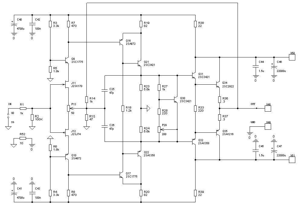
Here is another CFA from Norway.
( Från vårt broderland Norge ... han har en hel del bra läsning )
But it works in CLASS A and has got JFET, 2SK170 + 2SJ74 input.
LINK: Power Amplifier
The schematic:
Then the compensation is different for CF Amps.
The usual compensation small caps should be placed elsewhere.
But I never have learned and I am not sure how to put capacitors
to get best effect and keep 100% stable.
Best way is to look at some current feedback amps
and see where those small caps are.
And try to change value, if it does not work.
Here is another CFA from Norway.
( Från vårt broderland Norge ... han har en hel del bra läsning )
But it works in CLASS A and has got JFET, 2SK170 + 2SJ74 input.
LINK: Power Amplifier
The schematic:
An externally hosted image should be here but it was not working when we last tested it.
I think the simplicity of the amp is very interesting, but i'll think I'll dig into descrete input stages. It seems there is plenty of them around to learn a couple of things from.
My opinion is that even though Mr. Alexanders AES article is fairly old, there are'nt many of this amps with OPAMPS as input buffers (atleast I have not seen many), so maybe this is a fairly common flaw with this type of amp.
If I can recall correctly, the Alexander was issued after the Quad 405, which is also a current dumping amplifier, and the Quad works almost perfectly stable. Later amp is the super high slew rate Stochino amplifier which is a discrete symmetrical LTP input. Different animal but I guess it could be inspired by the current dumping also.
Quasar v13 is relatively a modern implementation of the Quad ideas. The problem is that the quality of such amps really depend on the opamp. The old LM301 as I thought used in the Quad 405 is very musical but is very noisy.
For me, it is hard to decide whether this kind of amp worth to be kept or not. The opamp is in class-A and with low gain, but I think it is really a test for everyone who can hear the terrible sound of an opamp.
Danish hifi magazine "high fidelity" did an DIY article on this amp. The magazine doesn't exist anymore. But the guys behind it, have an online mag now.
NOMONO | webmagasin om lyd, billede og musik
Perhaps they can help.
NOMONO | webmagasin om lyd, billede og musik
Perhaps they can help.
apples and oranges
The Alexander amp doesn't need a CMCL.
Huh? The Alexander amp is a current feedback amplifier.
[snip]
Also I tried to implement a CMCL but it did not seem to do any good really, maybe I did it wrong, gave it one hour or so... 🙂
The Alexander amp doesn't need a CMCL.
If I can recall correctly, the Alexander was issued after the Quad 405, which is also a current dumping amplifier
[snip]
Huh? The Alexander amp is a current feedback amplifier.
Post8 shows the NFB going to the input pair source resistors.
Does this feature make this a CFB amplifier rather than a VFB amp?
If not, then how does one define a CFB arrangement?
Does this feature make this a CFB amplifier rather than a VFB amp?
If not, then how does one define a CFB arrangement?
Post8 shows the NFB going to the input pair source resistors.
Does this feature make this a CFB amplifier rather than a VFB amp?
...........

When one reads the datasheet of a CFB opamp there are rules for the resistance of the various resistors that determine the gain and stability of the opamp.
When we look at a discrete CFB amplifier, can we use the opamp rules in any way to guide us to a stable and predictable power amplifier arrangement?
Or,
do we need a new rulebook specifically for the CFB amplifier in front of us?
When we look at a discrete CFB amplifier, can we use the opamp rules in any way to guide us to a stable and predictable power amplifier arrangement?
Or,
do we need a new rulebook specifically for the CFB amplifier in front of us?
Having spent some time in analysing the Alexander's amp structure, I concluded that it was quite conventional. What I did not know and confirmed my way of thinking is that Peter Baxandall has said the same much prior to me.
His comments on current feedback can be found in Talbot-Smith's "Audio Engineer Reference Book' :
"The term 'current feedback amplifier' has appeared in op-amp manufacturers'litterature (Ogden, 1992) since about 1985 and also in audio power amplifer context (Alexander 1990). It is implied that a new basic principle is involved, but really it is an old one in disguise [...]"
Actually, CFB power amps are older than the VFB counterparts. The very first transistorized power amps, that appeared in the sixties, had an input stage comprising only one transistor and the feedback was applied to the emitter.......
Huh? The Alexander amp is a current feedback amplifier.
You're right. I just found out last night that I have mixed them up when I accessed my circuit archive. Then it may be true that there may be a flaw with the Alexander amp, tho my friend who had built it didn't say anything about instability, only about good sound 😛
I think I will remove the Alexander amp from my project list 🙂 Replaced with Wavebourn Tower II voltage stage plus X-Pro quasi NMOS follower 😀
When one reads the datasheet of a CFB opamp there are rules for the resistance of the various resistors that determine the gain and stability of the opamp.
When we look at a discrete CFB amplifier, can we use the opamp rules in any way to guide us to a stable and predictable power amplifier arrangement?
Or,
do we need a new rulebook specifically for the CFB amplifier in front of us?
AndrewT.
Excuse for my nitpick 🙂
But as far as I know it..........
CFB = Complementary FoldBack = Sziklai
CFA = Current Feedback Amplifier
/regards lineup
Last edited:
Anyone simulated the current feedback amplifier by Mark Alexander?
When you simulated it, did you check that the model you were using for the input opamp dealt correctly with the power supply currents? Many (probably most) don't handle these correctly - Mark Alexander wrote a paper about that too - probably inspired by the problems he had trying to sim his amp😀
I haven't simmed it but I did build a variant of it a long long time ago. Made it fully bridged and used an INA103 as the input opamp. Sounded awesome but never got around to stabilising the bias currents - I changed the output stage to multiple paralleled logic-level MOSFETs for high gm.
- Status
- Not open for further replies.
- Home
- Amplifiers
- Solid State
- Alexander amp