> Wouldn´t the cap sort of compromise the CS function (as do the McMillans) in that it´s possible to have more current through the diff pair than the 10mA?
I presume you are referring to the 22uF cap I proposed.
If you were not using source degeneration, AND you have a balanced input, the source voltage (relative to ground) should stay pretty much constant even at full swing, so that the 22uF cap is not really charging or discharging from the CS. It is sort of restricted by the 3rd resistor, the value of which you have to experiment with.
The problem with the McMillan is that if you have common mode at the output (which I suspect), you get that 1:1 through the McMillans durectly into the diff pair.
It is more a voltage thing than a current thing. If you get what I mean.
Patrick
PS I take back my comment some time earlier that your source resistors make no difference. They do make a difference in common mode.
OK,
just one other thing cause I don´t know if I made that clear the last time.
I measure 0,15V at the sources (p-p) when there´s around 22x2x1.4= 60V at the output (p-p)
This is 0,25% (made a mistake last time)
This voltage fed through the McMillans is dependent on the value of the McMillans isn´t it?
If these resistors are 0,25% off (wich is possible with 1% MF) then you would also see a voltage at the sources wouldn´t you? Even if there´s no common mode distortion at all?
William
> If these resistors are 0,25% off (wich is possible with 1% MF) then you would also see a voltage at the sources wouldn´t you? Even if there´s no common mode distortion at all?
The answer is yes.
But then before we reject the common mode hypothesis, how do you explain the fact that this "distortion" you observed would disappear if you disconnect the McMillan resistors altogether ?
My proposal to add a thrid resistor and a cap is a sort of passive DC servo, if you like.
Patrick
Hi Patrick,
I don´t know if it would disappear cause my amp is not DC stable without them (I tried)
I will try your sollution and then maybe a real dc-servo without any McMillans......
William
I don´t know if it would disappear cause my amp is not DC stable without them (I tried)
I will try your sollution and then maybe a real dc-servo without any McMillans......
William
> I don´t know if it would disappear cause my amp is not DC stable without them (I tried)
If you meant that you have a DC drift over hours or minutes, then you can still do a quick test without them.
If you meant you have common mode oscillations with time period below 1 minute, then it certainly means that you have some more problems to solve, because the circuit should work without the Mcmillans.
Try removing them and loading the 2 outputs with say 33R 10W to ground (respectively).
Patrick
I just tried to remove the McMillan resistors and it seems it is working almost fine now. Now I can see a perfect sinus wave until 30vpk. I need to keep taking some more measures though.
Xavier
Xavier
Xavier,
have you remove the caps between C-B of q3-q8 ?
Which resistor do you use for R1-R4 and R44-R45? At the moment
I use 240R, but without Mcmillian resistor I do not known about DC offset 😕 😕 😕
Thanks Paolo
have you remove the caps between C-B of q3-q8 ?
Which resistor do you use for R1-R4 and R44-R45? At the moment
I use 240R, but without Mcmillian resistor I do not known about DC offset 😕 😕 😕
Thanks Paolo
Hi Patrick,
my current source setting pot and surrounding resistors is a bit "direct" because I just took out the parallel resistor to get the current down.
This makes setting the dc offset a bit tricky.
William
my current source setting pot and surrounding resistors is a bit "direct" because I just took out the parallel resistor to get the current down.
This makes setting the dc offset a bit tricky.
William
Taking the McMillans out did it for Xavier.
So it only remains my 3rd resistor + cap solution to try out ?
A servo is a bit more complicated, I think. And you should really do the servo by changing the reference voltage of the diff pair CCS so that it is sort of less invasive than adding current at the diff pair source directly.
Patrick
So it only remains my 3rd resistor + cap solution to try out ?
A servo is a bit more complicated, I think. And you should really do the servo by changing the reference voltage of the diff pair CCS so that it is sort of less invasive than adding current at the diff pair source directly.
Patrick
Hi,
I will try the third resistor plus cap.
A DC-servo is more or less ready but not tested yet (and if possible I would like to avoid it)
Without the McMillans is not possible for me as the startup dc-offset will be way too high.
Xavier,
how does it sound without the McMillans?
Hugo,
did some tests yet?
William
Originally posted by sinuko
have you remove the caps between C-B of q3-q8 ?
Which resistor do you use for R1-R4 and R44-R45? At the moment
I just removed the McMillans, leaving everything the same. The resistor to ground I use is 68R. The absolute offset starts at about +15v and after a while goes downto -1v aprox.
Although there is been much improvement, the behavior is still there, but starting after 30vpk.
The next thing I will try is to reduce the resistor to gnd to be able to reduce the offset and try to remove the caps between C-B of q3 and q8.
Xavier
William,
I did not plug the speakers yet. I want to make sure that the offset is under control first.
Xavier
I did not plug the speakers yet. I want to make sure that the offset is under control first.
Xavier
I used a variac and tried a few voltages between 20 and 30V.
I can’t reproduce the clipping like you showed in post #46 but noticed two things.
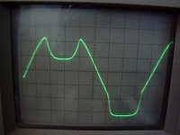
The first being a sagging of the waveform (at peak level) which is IMO due to current starving and a second being clipping (flat tops) which is just the sine wave bouncing at the rails.
In all cases this can be cured by either upping the bias and/or the voltage and the limit is determined by the heat sink capacity, long before the mosfets leave the SOA.
With lower rails, we have the luxury of more bias and I believe my amp hits the sweetest spot at about 24V, voltage and current wise.
The diff pair current source is build around a TL431 and when changing the rail voltage, I first trim both relative and absolute offset which surprisingly adjust very well together.
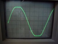
Then, I make the amp clip just a little bit and adjust the bias of both halves until I get a little flat line on both the upper and lower part of the sine wave. All measurements have been done with a dummy load.
All in all, I don’t think I presented something new.
First picture is what I call the current starving mode:
I can’t reproduce the clipping like you showed in post #46 but noticed two things.
The first being a sagging of the waveform (at peak level) which is IMO due to current starving and a second being clipping (flat tops) which is just the sine wave bouncing at the rails.
In all cases this can be cured by either upping the bias and/or the voltage and the limit is determined by the heat sink capacity, long before the mosfets leave the SOA.
With lower rails, we have the luxury of more bias and I believe my amp hits the sweetest spot at about 24V, voltage and current wise.
The diff pair current source is build around a TL431 and when changing the rail voltage, I first trim both relative and absolute offset which surprisingly adjust very well together.
Then, I make the amp clip just a little bit and adjust the bias of both halves until I get a little flat line on both the upper and lower part of the sine wave. All measurements have been done with a dummy load.
All in all, I don’t think I presented something new.
First picture is what I call the current starving mode:
Attachments
Hi Hugo,
did you test at 10kHz? My sine wave is perfect at 1kHz with nice clipping just as in your pics. Problems start at higher frequencies.
William
did you test at 10kHz? My sine wave is perfect at 1kHz with nice clipping just as in your pics. Problems start at higher frequencies.
William
Hi Hugo,
why can´t you get more than 22V? You should get over 30V eff out of your amp. At 22V mine doesn´t show this effect either.
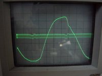
If I look at your power supply and the sinus there´s a dip in just the same place as in mine.
William
why can´t you get more than 22V? You should get over 30V eff out of your amp. At 22V mine doesn´t show this effect either.
If I look at your power supply and the sinus there´s a dip in just the same place as in mine.
William
William,
That's only because the bias was not set high enough.
As for the dip, I believe this is simply the way the AlephX clips. At least here, the sine wave is good up to the level where the clipping starts.
/Hugo
That's only because the bias was not set high enough.
As for the dip, I believe this is simply the way the AlephX clips. At least here, the sine wave is good up to the level where the clipping starts.
/Hugo
- Status
- Not open for further replies.
- Home
- Amplifiers
- Pass Labs
- AlephJ-X