Hi,
my ac-current gain is set at precisely 50%. The power into 8 ohms is voltage limited, not current limited. (100 watts 4R is the limit). I´ve tried removing R12/34 but this way the amp will be current limited into 8R.
I also think the cause is somewhere in the active current source but I´m not shure where.
The bias is around 7A wich should be enough
Removing the caps causes oscillation.
BTW I´m referring to the HifiZen schematic,
William
wuffwaff said:
my ac-current gain is set at precisely 50%. The power into 8 ohms is voltage limited, not current limited. (100 watts 4R is the limit). I´ve tried removing R12/34 but this way the amp will be current limited into 8R.
I also think the cause is somewhere in the active current source but I´m not shure where.
The bias is around 7A wich should be enough
From your spreadsheet, you'll need 8A for 8R (64W) without ac-current gain. Have you tried 25% and a little higher bias?
Hi,
I can try but this is no option for my speakers.
As this distortion is not appearant on 4R I think it is more voltage dependant as current.
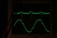
William (who is just taking pics of some square waves)
I can try but this is no option for my speakers.
As this distortion is not appearant on 4R I think it is more voltage dependant as current.
William (who is just taking pics of some square waves)
OK,
some more information:
1. with no load the distortion is the same at the same voltage.
2. with the active current source deactivated the distortion stays the same (removed R12/34)
3. with R14/31 from 1k5 to 2k7 the distortion stays the same
4. as soon as the distortion sets in you can see the dips on both power supply voltages as dips over 200mV big. This means that there are current peaks wich can only be caused by bias peaks wich are influenced by the whole current source
So somehow above around 22V output ( 31V peak, 15,5V per side) something happens causing the bias to peak. This happens twice per cycle.
William


William
The square waves look fine to me, so I don't think you have an oscillation problem.
The thing I find strange is that the rail dip occurs half way on the downward slope. If you have a differential probe, maybe you can check the output current. The fact that you still get this with the active current source deactivated implies that the latter may not be the cause.
The other measurement I would suggest, just to trace where it might come from, is to measure the voltage across the JFET drain resistors. Again you need to measure with a diff probe, since you need at least one channel at the output to show the phase relationships.
😕
Does it get worse with 16R ?
Patrick
OK😡 I think I´ve found it.....
looking at the voltage at the drain resistors there´s a strange peak when the distortion sets in.
Looking at the voltage before the source resistors there´s a sinus with almost 0,15V PP just before the distortion sets in. this means that Vgs is changing all the time and when the voltage reaches 0.25V it can´t go any higher, sort of clips and causes this distortion.
Taking ot R46/47 (I tried😀 ) is no option as the absolute dc offset get´s a bit unstable.
Changing them to 33k (from22k) makes things better at least until about 27V are reached (wich is almost at clipping)
If you look at the waveform at the jfet sources they start distorting a few volts before the output starts distorting because of the feedback keeping things together.
This also explains why changing the McMillan resistors to bigger ones made such a big sonic change.
So what to do next?
Put in a servo and very big (>50k)McMillan resistors?
Change all output devices to toshibas with lower input capacitance?
Put in the IRF9610´s again?
I could up the source resistors but I don´t think this is a good sollution.
Any ideas???😕 😕
William
Hi Patrick,
you answered while I was answered but I sort of did what you wanted Although my explanation might not be very scientific it certainly has something to do with Vgs reaching 0V and getting into the not so linear area.......
William
you answered while I was answered but I sort of did what you wanted Although my explanation might not be very scientific it certainly has something to do with Vgs reaching 0V and getting into the not so linear area.......
William
Hi, William
“Put in the IRF9610´s again?” ..
At the moment with 12 fet per channel (21.5 rail voltage) I have the same problem using irf9610. (In my case Mc Millian resistor are 4.7k).
Ciao Paolo

“Put in the IRF9610´s again?” ..
At the moment with 12 fet per channel (21.5 rail voltage) I have the same problem using irf9610. (In my case Mc Millian resistor are 4.7k).
Ciao Paolo
William,
I have done over-bias of JFETs as Borbely suggested to up to -0.3V for P-type JFETs and they do just fine. So going beyond Vgs=0 is not a problem for me. There are I am sure different opinions on that.
If I understand correctly, you are getting a high common-mode dynamic error from both outputs which got fed back through the so-called McMillan resistors. That implies you are operating the power MOSFETs in a region with relatively large even order harmonics. Changing to 2Sk1529 would not solve your problem. And the fact that Nelson is using JFETs with 40 FETs per channel means that the solution lies somewhere.
I remember that you are using 0R33 source resistors at the output stage. Try 0R47, as that would sort of linearise your output stage a bit and reduce this common mode error. Reduceing the 100R to ground at the outputs would probably have similar effects.
Another solution to cancel the even order harmonics (on each side of the X) is to drive the current source out of phase with the driver MOSFETs with a phase splitter, a la Linsley Hood. But then it would not be Aleph-X anymore.
Patrick
Hi Patrick,
I´ll try to explain the problem again:
looking at the source of the input fets everything is fine up to around 0,15V sinus.
At this moment this voltage sort of starts to clip but only at the sources, the output looks fine even when distortion at the sources (Jfets) is already heavy. For me this means that the McMillan resistors can´t deliver anymore current cause nothing is passing through because maybe Idss is already reached?
Raising the McMillan resistors, meaning less feedback to the sources makes things better. What has this got to do with the source resistors at the output fets?
William
Hi Paolo,
I had some great sonic succes raising those from 4k7 to 10k. Try this and see if the problem gets less (or maybe even is gone)
William
I had some great sonic succes raising those from 4k7 to 10k. Try this and see if the problem gets less (or maybe even is gone)
William
Sorry about that last one--some of the keys on my keyboard stick!
What I was going to say is that I find it very interesting that you are getting dips in you power supply voltage.
I think it would be safe to say the power supply's ability to output current at that point is being exceeded. But -- is it because of some fault in the power supply, or is it because the circuit is drawing a lot of "extra" power at that point? It would seem it must be one or the other.
You seem to be focusing on the amp circuit -- I am going to spend some time looking at the McMillan resistors to understand what you suspect may be the problem.
Very interesting thread......
JJ
So somehow above around 22V output ( 31V peak, 15,5V per side) something happens causing the bias to peak. This happens twice per cycle
If I understand the x-topology correctly, wouldn't the output on the other side be drawing peak current from the V+ rail? So it might only be once per cycle, shortly after the positive going peak?
JJ
> What has this got to do with the source resistors at the output fets?
Measure the total current through the diff pair when playing music, and you will see part of the music signal being feedback as current to the diff pair through them, as well as absolute DC. This is because the Id / Vgs of the output FETs are nonlinear. Although the diff amplitude is largely linearised by the bridged configuration, there is still a common mode component.
But I cannot visualise your description as yet, so I cannot be sure this is the cause of what you see. Give me a bit more time to think about this again.
Patrick
Hi Patrick,
also thought about this a few times this night. I know understand what you mean with common mode.
0,15V of 31V is about 0,5% right?
Could this common mode error also be caused by the R46/47 not being perfectly matched (they are "only" 1% resistors)
Could the fact that I´m using different source resistors (10R pot adjusted for minimal rel. dc offset) have something to do with it?
thanks,
William
> Could this common mode error also be caused by the R46/47 not being perfectly matched (they are "only" 1% resistors)
I doubt. I mean not too long ago, we only have 1% resistors. A circuit has to be designed to work with 1% component variations.
> Could the fact that I´m using different source resistors (10R pot adjusted for minimal rel. dc offset) have something to do with it?
Also not if you think about the diff pair as a monolithic components (black box). When driven by a CCS, it always deliver the same dynamic current at the output for a certain differential input voltage.
Send me a private email tonight. I'll send you some of my analysis of the Aleph-X circuit and how I deal with those issues. Not that you should follow my approach, but at least it might help to understand the current 'problem' better, I hope.
If we suspect that the JFETs are causing the distortion, it can only be two scenarios :
1) It hits a negative Vgs < -0.7V, and the gate conducts (the FET goes into reversed bias).
2) It bottoms out at threshold Vgs, i.e. not enough dynamic range.
That is why it puzzles me so much that you need so much dynamic range in the first place. I assume that you have at least 30dB NFB at 8ohm ?
Patrick
- Status
- Not open for further replies.
- Home
- Amplifiers
- Pass Labs
- AlephJ-X