Hi Patrick,
because of oscillations or to tune the frequency responce?
What is the bandwidth of your amp?
William
because of oscillations or to tune the frequency responce?
What is the bandwidth of your amp?
William
Hi Patrick,
that sounds good!
I´ll think about the 1529´s while cycling on Mallorca for the next ten days.
This evening the amps sound really nice with the JFet inputs.
cheers,
William
that sounds good!
I´ll think about the 1529´s while cycling on Mallorca for the next ten days.
This evening the amps sound really nice with the JFet inputs.
cheers,
William
Hi,
so after listening for a while with the last configuration I was still not happy with the lower bass. On tracks where this wasn´t a problem the sound was very good.
So the next step was to change the McMillan resistors from 10k to 22k.
This seems to improve things quite a lot (like going from 4k7 to 10k with the IRF9610´s). More bass and a nicer sound overall. Absolute DC ofset from cold doubled (as expected) to 7V but goes down quite fast.
Will leave it like this for a while and then change the drain resistors to 910R and source resistors to 5R (for dc offset).
I´ll also have to take a closer look at the high frequency behaviour at high currents.....
William
Hi,
this morning I did the next step:
Changed the drain resistors to 910R
Changed the source resistors to one 10R pot for setting dc offset (relative)
I also had to change a resistor in the current source to be able to set it low enough.
After this I had a look at the active current sources and C9 and C10. After reading this:
http://www.diyaudio.com/forums/showthread.php?threadid=98041&perpage=10&pagenumber=6
I tried some different values (In my case C9 and C10 where 3n3 for an optimal square wave)
So I started with 150pF:
frequency response 142/130kHz 8R / 4R
square wave has a little edge cut out of the leading edges
10kHz 4R is now better (16,6V) but starts oscillating after clipping
220pF:
almost the same as 150pF, square wave a bit better
330pF:
somewhat better behaviour but still oscillating after clipping
470pF:
no oscillation anymore
frequency responce 153/137kHz 8R/4R
10kHz/4R now OK until 19V (near clipping)
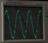
a strange thing was noticed on a pure sinus 10kHz into 8R (see pictures). I couldn´t get this away by raising the C´s nor by changing the feedback C´s from 5 to 10 or 20pF
680pF:
this showed the same behaviour as before (with the 3n3): The sinus into 4R (10kHz) went up to 15V or so and then suddenly broke down to something very awful.
the square wave showes some overshoot (small)
So at the moment I´ve put in the 470pF but although better, the behaviour at high voltages is still not OK. The square waves show some strange edges (most obvious at lower voltages) and the sinus at higher voltages has two dips in it.
I haven´t listened to it but I´m shure this won´t really matter at my normal listening levels but I would like it to go away....
any ideas?
William
this morning I did the next step:
Changed the drain resistors to 910R
Changed the source resistors to one 10R pot for setting dc offset (relative)
I also had to change a resistor in the current source to be able to set it low enough.
After this I had a look at the active current sources and C9 and C10. After reading this:
http://www.diyaudio.com/forums/showthread.php?threadid=98041&perpage=10&pagenumber=6
I tried some different values (In my case C9 and C10 where 3n3 for an optimal square wave)
So I started with 150pF:
frequency response 142/130kHz 8R / 4R
square wave has a little edge cut out of the leading edges
10kHz 4R is now better (16,6V) but starts oscillating after clipping
220pF:
almost the same as 150pF, square wave a bit better
330pF:
somewhat better behaviour but still oscillating after clipping
470pF:
no oscillation anymore
frequency responce 153/137kHz 8R/4R
10kHz/4R now OK until 19V (near clipping)
a strange thing was noticed on a pure sinus 10kHz into 8R (see pictures). I couldn´t get this away by raising the C´s nor by changing the feedback C´s from 5 to 10 or 20pF
680pF:
this showed the same behaviour as before (with the 3n3): The sinus into 4R (10kHz) went up to 15V or so and then suddenly broke down to something very awful.
the square wave showes some overshoot (small)
So at the moment I´ve put in the 470pF but although better, the behaviour at high voltages is still not OK. The square waves show some strange edges (most obvious at lower voltages) and the sinus at higher voltages has two dips in it.
I haven´t listened to it but I´m shure this won´t really matter at my normal listening levels but I would like it to go away....
any ideas?
William
Attachments
With so much information, I GUESS you might still have too much high freq gain. What cap do you have parallel to the feedback resistors (100k) ?
It would help the diagnosis if you can do a frequency response sweep from say 100Hz to 500kHz or 1MHz.
Patrick
It would help the diagnosis if you can do a frequency response sweep from say 100Hz to 500kHz or 1MHz.
Patrick
Hi Patrick,
the feedback caps are 5pF. I also tried 0, 10 and 22pF.
0pF made the square wave overshoot with some ringing
22pF rounded the square wave and reduced the frequency responce to 65kHz / 8R
I will do a frequency sweep tomorrow (this morning I looked at 20, 100, 1k, 10k, 20k, 100k and the -3dB point. Nothing unusual here)
thanks,
William
In my setup I am now using 10p, but I have tried 5p and apart from a slight overshoot at 10kHz square wave, I can probably get away with that, even 3.3p.
Caps at the current source is the same as yours, 470p. But I don't use the bootsctrap cap and I have batteries. So it is not 1:1 comparison.
And I don't do my tests close to clipping. I usually test at 4V from rail max. IMHO, you need to give the FETs a few volts or they get into a region where their capacitances jumps up enormously, and many funny things happen there.
But maybe Nelson would what to comment on that.
Patrick
PS Freq Sweep up to 100kHz won't be enough if you have excessive gain at say around 300kHz. That is why you need to go further to at least 500kHz. But a 20kHz square wave (overshoots) will tell you whether you have a HF problem or marginal stability.
Hi Patrick,
I did my tests at 1V, 10V and close to clipping. At 1V, 10V there´s no problem to be seen (except for the funny square wave, will take a pic tomorrow)
Only starting at about 20V/10kHz into 8R the funny sinewave starts to show getting worse at higher voltages.
4V from rail max would be 2x (22-4) = 36V peak so about 25-26volts eff.
What I don´t have used is C7 and C8 but I don´t think anybody used them.
William
William-
How are you measuring the output -- is that a summation of the voltages at each side of the resistor?
JJ
How are you measuring the output -- is that a summation of the voltages at each side of the resistor?
JJ
Hi,
I´m using two methods:
1. with two probes, one for each output, then added at the scope.
2. with a sym. to unbalanced converter (INA134) fed with the +out and -out via a resistor network and then with a single cable to the scope
Both are good enough to look at waveforms, the measuring of the ac voltage is performed by an old Fluke device.
William
SWEEP
Hi Patrick,
here´s the sweep into 8R:
20Hz 10,19V
50Hz 9,88
100Hz 9,88
1k 9,90
10k 9,91
20k 9,91
50k 9,67
70k 9,29
100k 8,70
150k 7,18
200k 5,32
300k 2,73
400k 1,43
680k 0,5
840k 0,35
1160k 0,16
1500k 0,05
No rising in between points. Measured with a Fluke 8500A and watched on a 20MHz scope. Measured with two probes.
Nothing I can see here.
Also checked the input signal wich is kind off flat until way over 1MHz and doesn´t show the distortion.
William
Hi,
I also checked at 22.5V where the distortion already shows.
With rising frequency the two dips walk towards the 0V line and reach it at around 40kHz. Checking up to 1.5MHz there were no signs of oscillation.😕
William
P.S. I almost forgot: The sound is very good at the moment. The mids and highs have gained quite a bit in the way different textures (sound colours and nuances are played).
William,
Can you post a square wave response ?
Just use the 1kHz square wave from your scope calibrator.
Also do you have a means to generate a balanced input ?
And try to measure one input (say +Vin) and one output (say +Vout) with your scope and see how the input looks like when you have this distorted sine.
I am a bit puzzled this time as well.
But still, I am glad you like the sound. 🙂
Patrick
Patrick,
square wave is possible but not spectacular (and I have to carry the amp up two stairs again......).
It looks very normal at 1kHz / 10V .
It still looks good at 0,5V but here you can see a very small edge cut out of the square waves edges (ca 2-4% of the height and width).
I do use a balanced input (DRV134) and checked the waveform when connected to the amp (was OK) but I will have a look again.
Manuel,
it´s a standard Aleph-X with 12 Fet´s/ channel and 100w / 8R. The only thing changed at the moment are the input fets from IRF9610 to 2sj74.
William
Hi William,
Did the behaviour you are describing appeared after you changed the frontend to jfets or it could be something that was there even before you did that change, as we are experiencing me and Paolo (sinuko)?
Did you check the output of each side of the monoblock refered to ground when the sinus wave is like the one you show in your last picture? In my case, I noticed that each side of the amplifier were clipping only at the positive pole, but not at the negative.
The cap just improved things but the behavior is still not perfect for high frequencies. I really don't know what is causing this distortion, but it seems that it is comming from the CCS. Please keep us updated on your progress.
Xavier
Hi Xavier,
yes I looked at both outputs. They showed the same behaviour.
An Aleph never clips on the negative pole because if it weren´t for the current limiters (Q4, Q9 plus resistors) it would sink as much current as your load allows for.
This behaviour wasn´t appearant before I changed to Jfets (although I´m not 100% shure)
Maybe I also have to look at R14/15 and R31/32 again.....
William
Hi William,
Referring to the sine wave in your post 46, I think the dips on the falling edge is caused by over-Aleph current and the distortion at the tips is caused by the slow response of the CCS or not enough bias.
Try these if you have not done so:
(since you did not post the schematic, I'm using Grey's diagram dated 5/24/02)
1. Replace R12 and R34 with a higher value (say 1.8K or use a trim), this will lower the Aleph current.
2. Remove any cap on B-C of Q3 and Q8.
3. If no effect on step 2, increase bias by increase VR1 and VR3, this will cure the distortion at the tips.
- Status
- Not open for further replies.
- Home
- Amplifiers
- Pass Labs
- AlephJ-X