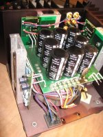
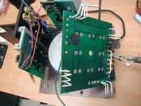
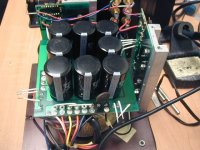
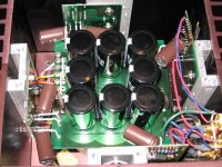
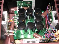
to ease removing wire from pad ( then cleaning pad from solder is piece of cake with solder sucker ) - add some new solder to connection , to achieve better and faster transfer of heat from iron
x2, this should solve your problem. use a tip with good thermal mass, add a touch of flux to the joint and then flood with solder while pulling the cap, works for me even on large psu caps with ground planes
Thanks to all the hints.
I got a 100W soldering gun from my colleague and all 8 caps are out in 30 minutes. I guess sometimes brutal force works. 😛
(I did use new solder to flood the pad and nice suction. But the chisel tip of 3mm and Metcal 40W RF soldering station still not pull the trick. I have not tried the large thermal mass yet since the soldering gun did them all.)
Now I am renewing all the soldering joins.
BTW, could someone provide a quick info on how to measure the capacitance >10mF? I read something about using function generator and scope via time constant route. Is that ok?
Last edited:
In my opinion, for this case the exact value is irrelevant. If you are buying the replacement caps new and from reputable manufacturer and vendor, most likely the capacitance is within the nominal value and tolerance range.
However, if you want to test each capacitor before soldering it, connect it to a power supply, having a resistor and amp meter in series. The resistor will limit the current during the charging period, the meter should stay at 0 A after charging, showing there is no leak. After finished testing, discharge the capacitor with a resistor before soldering it.
However, if you want to test each capacitor before soldering it, connect it to a power supply, having a resistor and amp meter in series. The resistor will limit the current during the charging period, the meter should stay at 0 A after charging, showing there is no leak. After finished testing, discharge the capacitor with a resistor before soldering it.
"BTW, could someone provide a quick info on how to measure the capacitance >10mF? I read something about using function generator and scope via time constant route. Is that ok? "
you can do it yes. pain in the butt. math sucks.
but you use R C time constant formula........
t=RxC time =resistance x capacitance. off the top of my head 1 time constant was 60 some % of charge (is that right?) and then the next tc would be 60% of what is left and so on...kinda like a half life of a element.
so you charge a cap through a resistor and see how many time constants it takes to reach 99ish% of charged and divide by the resistance.....i think. i did it once to say i did and could if i had to. but kinda forgot cause i got a fluke that did it for me.
maybe someone can confirm this before you try it.
it maybe useful to know how in the future however, in this application, grimberg gave some good advice.
I didn't worry about the new ones. I'd like to know how much the "old ones" have been off, if any.
Same thing for both capacitance and ESR.
As for ESR, I read somewhere a kit that you can built to measure ESR and very low resistance accurately.
I put all 8 old caps upside down on a flat surface, and they did wobble. The new ones don't. Maybe this wobbling test can indicate something. 😀
And one of the small coupling cap has some black sticky stuff at the base, I don't think that is glue. More like melted stuff or something from the inside...
Now all new caps are in place, I'll see if I have time to replace the coupling cap this weekend. Quite busy recently.
Same thing for both capacitance and ESR.
As for ESR, I read somewhere a kit that you can built to measure ESR and very low resistance accurately.
I put all 8 old caps upside down on a flat surface, and they did wobble. The new ones don't. Maybe this wobbling test can indicate something. 😀
And one of the small coupling cap has some black sticky stuff at the base, I don't think that is glue. More like melted stuff or something from the inside...
Now all new caps are in place, I'll see if I have time to replace the coupling cap this weekend.
 Quite busy recently.
Done with all my responsibility throughout the weekend. Finally I had a chance to work on the recapping. I found two coupling caps leaking on the pcb. Definitely make my effort worthy now.
After joggling with the reconnection of wires, I finally put it back together. Turning on the amp and saw the familiar blue LED... a good sign.
Then put it back into my system, immediately I head great positive things: the edgy and harsh top end disappeared and bottom bass show up nicely. Now I'll let the caps to burn in a little bit and report back later.
Thanks to all the helping hands here, especially ZM.
After joggling with the reconnection of wires, I finally put it back together. Turning on the amp and saw the familiar blue LED... a good sign.
Then put it back into my system, immediately I head great positive things: the edgy and harsh top end disappeared and bottom bass show up nicely. Now I'll let the caps to burn in a little bit and report back later.

Thanks to all the helping hands here, especially ZM.

I knew it is coming. 😀
It was too late and I hate to take off my headphone until too late. The photo of the whole process will be up soon...
It was too late and I hate to take off my headphone until too late. The photo of the whole process will be up soon...

Last edited:
I have listened to this recapped Aleph 3 for two nights. The low bass and bass impact is very nice now. The bottom end has lot more amount than it did before. I am happy for the positive change.
However, the mid/high end seems to be dried up a little bit. I did not use any bypass cap yet. I used 470uF to replace 220uF. Did that change the SQ? Now I'd like to try adding up some bypass caps to the caps in the signal path (C101 & C103) as ZM suggested.
I did find some MKC cap but quite expensive and with only 100nF available:
0.1uF/100V and 0.1uF/63V
Other suggest WIMA MKP may also be good replacement. They do have plenty value to choose from at mouser.
10-100nF/100V
Others suggest polyphenylene sulphide, 100nF/63V available at mouser
I'll get a few kinds for experiment if they do improve the mid/high sweetness.
Are those all good choice? And with what I want to improve on SQ, should I use 10 or 100nF?
Thanks!
Thanks for the confirmation on MKC. And I do feel the SQ at this moment was kind of "fluctuating". Sometime, it sounds wonderful, but the next day the magic wasn't there anymore. Then it sound great some time later. Amp was always warmed up for more than 1 hr. Hopefully this is due to some burn in.
just in case - did you checked bias , after recap?
changing caps will not change bias , off course , checking these things is general practice
changing caps will not change bias , off course , checking these things is general practice
ZM, thanks for more hints. The Aleph 3 service manual mentioned:
so I never look into the adjustment. I guess that you meant to measure some voltage to make sure things are right? such as
I'll do that tonight to make sure. Thanks!!
There are no adjustments to the amplifier. Values for biasing various components are taken from physical constants, such as pn junctions and zener voltages, and through matching of Mosfet transistors.
so I never look into the adjustment. I guess that you meant to measure some voltage to make sure things are right? such as
and other voltage noted on the schematic?The voltage rails of the supply are at 25 volts,
5 volts across R106.
R108 shows the drive voltage for the output stage, and it should have 4-5 volts
I'll do that tonight to make sure. Thanks!!
to measure Iq , just measure voltage across R120 , or R121 , or R122 , or R123
on output pcbs , these are big honkers near to output mosfets , not these one near to edge of pcbs
you can expect around 500mV across each of them , meaning that Iq is 1A per pair , totaling in 2A per channel
checking that is just standard procedure , same as checking output offset
on output pcbs , these are big honkers near to output mosfets , not these one near to edge of pcbs
you can expect around 500mV across each of them , meaning that Iq is 1A per pair , totaling in 2A per channel
checking that is just standard procedure , same as checking output offset
Last edited:
All volts across R120-R123 are about 0.48 V.
And other volts on the schematics were verified. The only number seems to be slightly high was the volt across R106, which was about 5.5V for both channels. (spec 4-5V on schematic)
And other volts on the schematics were verified. The only number seems to be slightly high was the volt across R106, which was about 5.5V for both channels. (spec 4-5V on schematic)
And tonight Aleph 3 has been pretty behave. The mid is sweeter and more vivid. Keep burning in. 😀
- Status
- Not open for further replies.
- Home
- Amplifiers
- Pass Labs
- Aleph3 recap

