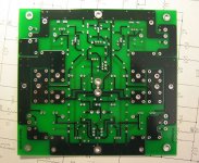
Nice looking boards! what are all of the dimples over the boards, on the traces and around the pads. Do they serve any purpose?
--
Brian
--
Brian
The dimples are vias connecting the top foil to bottom on the high current traces. The solder mask goes right over them, since they're not component holes. They are there to ensure good current sharing between the two sides, better HF properties (?) and improved mechanical characteristics. Not that they boards would be any worse without them... plus they look cool. 🙂
Last call!
OK, last call for orders on the rev 1.0 boards. As stated previously, I will be freezing the order quantity tomorrow (Nov 26.) at 5:00pm, PST. Orders after this time will go on the list for spare boards, on a first-come, first-served basis.
Revision 1.0 order count is now over 200(!), so the price is continuing to drop. It is now down around $7ish per board.
Please do not send me any money yet! I will send out full instructions tomorrow when the quantity and price are fixed.
I have a question regarding the size of C2 and C4. These are feedback caps which should be 5pF (this value works better in my circuit than 10p). I was using silver micas with lead spacing no more than 5mm, yet, from what I see on a board, available spacing is much bigger. Also similar for C7, C8: 5mm spacing should be possible for all those caps.
What type of caps did you have in mind when designing the board?
What type of caps did you have in mind when designing the board?
Peter,
good point, to be honest with you I was rather random in my choice of cap sizes. I went under the guideline that more space is better than less. I tried to put in extra pads to get a range of spacings. I may very well have overdone it. That is why this is called a prototype.
Chad and I are in the process of correcting all this stuff. I think that by the time we are done populating the proto boards there will be much more to change, hopefully not too much.
Anyways, I can't take my eyes off this board call it fatherly love. Like Pino Daniele said "Ogni scarrafone e' o bello a mamma sua". Stefano can translate that for you.😉
PS: since you are much more up do date on component sonics than I am, could you please post what cap you used brand model and source, if US applicable.
I would be inetersted in things like the snubbers you put on the rectifier diodes and other tricky components.
Somebody did really nice pictures of this boards (I like the schematic's bacground😉 ). I think the most tricky part will be choosing proper value for source resistors. It would be nice to aim at 0.5V drop, yet current is pretty much dependent on the heatsinks (if you want to keep them at 50 deg C). I have 4 pairs per side and used the value of 0.56 ohm, yet I had to lower the current and the actual drop is around 0.42V. The feedback cap I'm using is 10p, yet the square wave looks better with 5pF. It's silver mica from Digi-Key. I'm using 4k7 sources to output DC comp resistors and the value of 100ohm (10W Dale) for absolute DC offset correction resistor (otput to ground). The offset is very stable so I think those values are pretty much correct. I'll try today to omit the 100ohm resistors and see what happens.😉 I didn't use lag capacitors (didn't even try to put them in a circuit). Most of the values of the resistors are according to the circuit posted by rtirion. I used 220k resistor in the feedback loop, 33K input to ground resistor. Initially I had 68K, but Nelson advised me that lower value is prefferable. My gain is around 26dB.
I noticed that input caps have big influence on DC offset. Initially I was using 2uF and -3dB was at 8Hz. I'm using now 0.06uF for high pass filtering at 140Hz (for bi-amp system). The values of the caps had to be the same on both sides. If I placed 0.06 on positive input and 2uF coupling negative input to ground, I got hum. Also my BOZ has a cap at the output, yet when I shorted the cap on posistive input the offset jumped to 300mV.
When I shorted the negative input to ground cap the offset jumped to something like 1V.
I'm using thermistors between the cap banks and they work pretty well. Also I have soft recovery diodes from Dig-Key and 0.33u caps across ea. (this was tha value I had at hand).
Thanks Peter, the part about the input caps is most interesting, I have already observed that in the past with, for example, the Hiraga le classe A, temperamental little circuit, and some other similar current feedback designs.
I thought it may be due to the two chassis having different grounds and the cable length, some DC builds up somehow.
I thought it may be due to the two chassis having different grounds and the cable length, some DC builds up somehow.
Peter,
Thanks, I took those pics yesterday when the boards arrived using my Canon S30. Digital cameras are so handy sometimes...
The DC offset you talk about, is that absolute DC offset, or DC differential between the speaker outputs. If it's only absolute DC level, then perhaps the coupling caps aren't super important, but if it's a DC voltage that will appear across the speaker, then it's cause for greater concern.
As far as the cap footprints go, I was planning to use the axial polystyrene types, which would fit very well in the footprint we used. The compensation cap footprints for the current sources are smaller, in order to take less room on the board, and are more suited to a radial style cap.
Beta order update
Now for a little news...
The beta boards shipped this morning. All were sent USPS Priority Mail or Global Priority, except one of the international shipments. For US addresses, expect to see the boards in 1-3 days, international in 4-6 days. For those who paid by cheque or money order, I've included a cheque for your surplus funds. Those who paid by PayPal will receive their surplus funds back tonight, by PayPal. Most people will be getting $16-$25 back on their order.
Rev 1.0 order close...
I'll be freezing the order quantity for the rev 1.0 boards in about an hour. At this time, I have a large quantity of emails to respond to, so if you haven't heard back yet, please don't panic and send me 6 urgent messages that I haven't replied! I'll be responding to everyone tonight so by tomorrow you should know if your message got through. Don't sweat it if you didn't make the "deadline"... it's more of an informal mechanism to help me control the order. I have to draw the cutoff somewhere, otherwise orders would just keep flooding in.
Order details and payment info will be going out by email tonight as well.
hifiZen said:
The DC offset you talk about, is that absolute DC offset, or DC differential between the speaker outputs. If it's only absolute DC level, then perhaps the coupling caps aren't super important, but if it's a DC voltage that will appear across the speaker, then it's cause for greater concern.
As far as the cap footprints go, I was planning to use the axial polystyrene types, which would fit very well in the footprint we used. The compensation cap footprints for the current sources are smaller, in order to take less room on the board, and are more suited to a radial style cap.
The offset I was talking about is between speaker terminals. The absolut offset changes quite a lot in the beginning in a range of 3-4V but after a while it settles down and can be easily adjusted with CCS trimpot. The offset between terminals is always below 10mV; not bad, is it? 🙂
Lots of people are using silver mica 10p or 5pF for feedbac cap and spacing required is 5mm. If there is space on a board it would be nice option.😉
10mV is pretty good indeed! 🙂
With respect to the feedback cap, I think grataku has done some revisions to the board, and added this feature.
With respect to the feedback cap, I think grataku has done some revisions to the board, and added this feature.
Order update!
OK, rev1.0 ordering is now closed, and the final quantity requested is... wait for it... 300!! So, it looks like I will be ordering 340 PCBs, which will be a 19kg (41 lbs) shipment, and order cost totals over $1600 USD!!!
Individual board cost is now at $5.10 USD each + shipping from factory to me, which I am still calculating. Please do not pay me based on this amount yet! I will calculate exact amount and send it in the email. I don't want to have to send refunds to anyone for excess payment, like I did for the Beta order...
I received a flood of email just before the deadline, so I'm still busy replying to the individual mails. So, to help me cope with this huge order, please follow the directions in the "order details" message carefully. I'll be sending it out soon.
Order volume may cause delay...
Actually, there are so many orders I will have difficulty handling all this on schedule. It's a bit more than I bargained for!
As the price dropped, more orders kept pouring in, faster and faster. This is why I had to cut it off at some point! But, I'm tempted to re-open orders for one more week. This would save me a lot of stress by postponing the manufacturing for delivery to me after I return from Christmas vacation. Then I can deal with the shipping without the strict Christmas deadline looming. It would also allow me to do a better job testing my prototype version. I would be able to ship them out to everyone about mid January (probably the 15th). If we do this, the boards will cost even <i>less</i>, and would give grataku and I more time to do a better job on the revisions. As it is, there is very little time left to build and test the Beta boards before the design needs to be finalized for rev1.0. We only have until Dec 8th to get it done! It's doable, but there's no room for slack. Moving the ship-out date to mid January would also mean that we can go to a longer lead-time on the production, bringing the cost down even more!
What do you think of moving the production schedule back? It sure would relieve some stress for me... If anyone has strong objections, please email me. In the meantime, I'll discuss this more with grataku and post the decision very soon.
I'm going to delay the details email until Grataku and I have reached a decision on this, which I promise to do quickly... Thanks everyone for your patience.
My opinion: take you time. This is not buisiness, so time shoud´nt be the point. Qualitiy is important, and for most of us (me) price too.
I think the most of us haven't the other parts yet, they order the board's because it's an offer they can't refuse 🙂
I'd gladly order some boards (4) but I also would like to know how to pay (Paypal?) and how much would it cost delivery to Italy.
So if you keep accepting orders for another week.... 😀
Andypairo
So if you keep accepting orders for another week.... 😀
Andypairo
Chad,
Just a thought, take your time to do a better board, and on the shipping side of things, would it be better to send to one person of a location so that the few people around that location can share the cost of custom brokerage fee, duty tax, and shipment cost, personally I don't mind to drive an hour or so to town to pick it up.
Just a thought, but then someone in a location has to do the local distribution.
Regards,
Chris
- Status
- Not open for further replies.
- Home
- Amplifiers
- Pass Labs
- Aleph-X Official PCB rev Beta & 1.0