Re: steal the best
For my diy amps,
my small budget allows me to buy the best components
available here even though they are not world-wide best.
😀
Ramandi said:I like to go with the best components available . . .
For my diy amps,
my small budget allows me to buy the best components
available here even though they are not world-wide best.
😀
Absolutely right Patrick, although one mostly seesNelson's is the best, the rest are all mess-around mock-up's.
Panasonic parts in his amps. Being good solid components, they dont count as being exotic. You dont see outragously expensive parts in Pass amps. As usual, its the circuit that sings, not the parts 😉 You can go for expensive audiophile parts throughout and end up with an amp that costs 1/2 a million, sounding a fraction better (with a little good will😀 ) than one costing 2K$.
I am not saying that you should skimp on quality, just that its plain crazy to spend several hundreds of $ on a single cap.
Good solid quality standard parts, is the way forward.
Steen🙂
Chasing the hum out of my aleph-x
Dear aleph-x builders, maybe one of you can help me with a problem I cannot solve despite reading all your posts.
I recently finsihed a pair of low power aleph-x monoblocks, they both worked at once and sound amazing! Best amps I have built, even compared to my zen V9!
Specs are: 14.3 V rail voltage, one rectifier bridge per channel, CRC filter with 3x 22mF, 0.2 ohm resisitor (5x 1R) followed by 2x22mF caps. 4 IRFP044 per channel, bias is 4A per side, current source set around 50%, relative offset around 20mV. I guess it is a typical low power configuration.
The problem is that one of the channels has a slight hum coming out of my 96db efficient speaker, while the other monoblock is absolutely quiet. By exhanging transformers, power supply, rectifiers and output boards between the two monoblocks I narrowed down the problem to the mainboard of the humming channel.
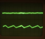
Here comes the strange thing that puzzles me: When I look at the output of the humming channel I see the following: The there is 100Hz oscillation only at the + output (measured to ground), the - output on the humming monoblock looks just like the + and - outputs of the silent channel. (+ output is the bottom trace and - output the top trace in the picture below). Amplitude of the oscillation is around 20mV.
How can it be that PS noise shows up only on one side (the + in my case) of the output?
Any suggestions for troubleshooting?
Thanks for any ideas.
Dear aleph-x builders, maybe one of you can help me with a problem I cannot solve despite reading all your posts.
I recently finsihed a pair of low power aleph-x monoblocks, they both worked at once and sound amazing! Best amps I have built, even compared to my zen V9!
Specs are: 14.3 V rail voltage, one rectifier bridge per channel, CRC filter with 3x 22mF, 0.2 ohm resisitor (5x 1R) followed by 2x22mF caps. 4 IRFP044 per channel, bias is 4A per side, current source set around 50%, relative offset around 20mV. I guess it is a typical low power configuration.
The problem is that one of the channels has a slight hum coming out of my 96db efficient speaker, while the other monoblock is absolutely quiet. By exhanging transformers, power supply, rectifiers and output boards between the two monoblocks I narrowed down the problem to the mainboard of the humming channel.
Here comes the strange thing that puzzles me: When I look at the output of the humming channel I see the following: The there is 100Hz oscillation only at the + output (measured to ground), the - output on the humming monoblock looks just like the + and - outputs of the silent channel. (+ output is the bottom trace and - output the top trace in the picture below). Amplitude of the oscillation is around 20mV.
How can it be that PS noise shows up only on one side (the + in my case) of the output?
Any suggestions for troubleshooting?
Thanks for any ideas.
Attachments
Re: Chasing the hum out of my aleph-x
check input CCS (on top of LTP) and check all tiny parts around output CCS
with "check" I mean- resolder them and-if that didn't help,change them one by one
1001meier said:Dear aleph-x builders,..................
check input CCS (on top of LTP) and check all tiny parts around output CCS
with "check" I mean- resolder them and-if that didn't help,change them one by one
Wow, that's a fast reply.
Just for my information, what is LTP? (CCS I figured out)
So I need to take the shotgun approach....
Just for my information, what is LTP? (CCS I figured out)
So I need to take the shotgun approach....
1001meier said:Wow, that's a fast reply.
Just for my information, what is LTP? (CCS I figured out)
So I need to take the shotgun approach....
hehe........ya made X and don't know what is LTP.....certainly hole in approach

anyway-LTP means Long Tailed Pair......these two funny mosfets on input of your X....just bellow that input CCS.....
I am by no means an Aleph X pert 😀 But if I recall, this amp has what is know as "Mcmillan" resistors, connected to the sources of the diff pair? Check those 😀
Just a thought...
Just a thought...
Zen Mod said:
hehe........ya made X and don't know what is LTP.....certainly hole in approach
...exactly, goal is to understand how things work by building them (and troubleshooting).
Thanks for your help!
flg said:I am by no means an Aleph X pert 😀 But if I recall, this amp has what is know as "Mcmillan" resistors, connected to the sources of the diff pair? Check those 😀
Just a thought...
yes, good idea. I am using 2.2K "Mcmillan" resistors.
Re: Re: Chasing the hum out of my aleph-x
One more question after scratching my head: How could input CCS be the culprit since it is shared by both sides and the hum only shows up on + side? Moreover, inputs on - side is free of hum, looks just like + input.
Zen Mod said:
check input CCS (on top of LTP) and check all tiny parts around output CCS
with "check" I mean- resolder them and-if that didn't help,change them one by one
One more question after scratching my head: How could input CCS be the culprit since it is shared by both sides and the hum only shows up on + side? Moreover, inputs on - side is free of hum, looks just like + input.
Good question!
So check the rest. It will probably be in the +out power section of the amp. A mistake in the diff pair would also show up on both sides.
I woulk also think it´s a bad solder connection.
William
So check the rest. It will probably be in the +out power section of the amp. A mistake in the diff pair would also show up on both sides.
I woulk also think it´s a bad solder connection.
William
Re: Re: Re: Chasing the hum out of my aleph-x
remember-that's X.....twisted in phases and feedbacks
but-also mea culpa,I didn't meant just on input CCS,but also on LTP
you have problem;
just heat your Iron and go for it ;
when you find what is ,I'm sure that you'll laugh .
probably nobody from forum can't tell you what is fer sure.
you can start from output current source(s),if you wish
1001meier said:
One more question after scratching my head: How could input CCS be the culprit since it is shared by both sides and the hum only shows up on + side? Moreover, inputs on - side is free of hum, looks just like + input.
remember-that's X.....twisted in phases and feedbacks
but-also mea culpa,I didn't meant just on input CCS,but also on LTP
you have problem;
just heat your Iron and go for it ;
when you find what is ,I'm sure that you'll laugh .
probably nobody from forum can't tell you what is fer sure.
you can start from output current source(s),if you wish
1001meier,
Since you have an oscilloscope, you can start at the +output and trace your way back to the input or up through the output CCS and find where the hum starts to appear on the scope. That's where you start you search for the noisy cold solder or bad component.
Allan
Since you have an oscilloscope, you can start at the +output and trace your way back to the input or up through the output CCS and find where the hum starts to appear on the scope. That's where you start you search for the noisy cold solder or bad component.
Allan
Blues said:1001meier,
Since you have an oscilloscope, you can start at the +output and trace your way back to the input or up through the output CCS and find where the hum starts to appear on the scope. That's where you start you search for the noisy cold solder or bad component.
Allan
Hi Allan,
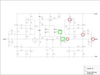
this is exactly what I have been doing the past few days. In the attached diagram I indicated with red circles the noisy region and green squares the quiet parts. It looks like noise enters after the feedback capacitor (C4)/ resistor (R30). I already changed Q8 without improvement.
So it seems like the CCS is the source of trouble?
Great forum, glad to get all this feedback and hope it will help others!
Attachments
wuffwaff said:Hi,
do you have a compensation cap in the CCS?
William
Not sure which cap you mean. Could you please explain a bit more. I have all the caps shown in the circuit. By the way, I am using BC550 instead of MPSA18 transisitors.
1001meier said:
Not sure which cap you mean. Could you please explain a bit more. I have all the caps shown in the circuit. By the way, I am using BC550 instead of MPSA18 transisitors.
C102 and C105 on attached pic
C102 maybe can solve your problems
if not-change both - BC and IRF in that CCS
Attachments

I don't see the McMillan R's in that schemo???
2.2K would possibly be the value??? Post #134???
😀 😀 😀
But, then again, those R19-29 guy's???
You aren't running a single ended input are you???
😀 😀 😀
2.2K would possibly be the value??? Post #134???
😀 😀 😀
But, then again, those R19-29 guy's???
You aren't running a single ended input are you???
😀 😀 😀

flg said:I don't see the McMillan R's in that schemo???
2.2K would possibly be the value??? Post #134???
😀 😀 😀
even if I didn't make any X yet,I'm not sure that lack of McMillan's can be culprit for that ripple;
without them DC behavior of circuit is certainly degraded ........in any case-that's first Gray's schematic,from era without McMillans....
I'm pretty sure that meier have them in place..........
I'm still with bad solder point ,or defective bjt or output mosfet ,as culprit for his problems......
he will tell us,I hope....when he find what is........
- Status
- Not open for further replies.
- Home
- Amplifiers
- Pass Labs
- Aleph-X monoblocks finished.