Peak-to-peak voltage swing of Aleph-X
I can't see how the peak positive output of the Aleph-X can get closer than 4 Volts to the positive rail, since the Gate voltage on Q1 (and Q10) needs to be Vgs above the Source. If the highest Gate voltage is almost equal to the rail, then the Source is at the rail, less Vgs and the output is a bit low.
And if the positive rail is limiting the output, the negative swing equally can't go closer to the rail (well, not without distortion).
With additional voltage losses in the biasing and output resistors, you would surely need to have the rails at least 5 volts higher than peak output voltage - ie with rails of +/- 15 Volts, you would get a voltage swing of 2 x (15V - 5V) = 20V peak-to-peak.
Into a 8 ohm load this gives 25 watts RMS - calculated as (20/1.41)^2 / 8.
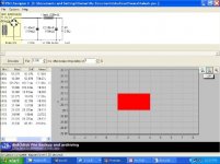
The "X berekening v2" spreadsheet assumes that peak-to-peak output voltage is 2 x rails less 4 Volts - and hence shows 26V peak output voltage and power of 42.25 watts RMS.
Am I missing something 😕 😕 😕 Does C1 operate in mysterious ways?
Has anyone measure/simulated the actual swing ?
Nic
I can't see how the peak positive output of the Aleph-X can get closer than 4 Volts to the positive rail, since the Gate voltage on Q1 (and Q10) needs to be Vgs above the Source. If the highest Gate voltage is almost equal to the rail, then the Source is at the rail, less Vgs and the output is a bit low.
And if the positive rail is limiting the output, the negative swing equally can't go closer to the rail (well, not without distortion).
With additional voltage losses in the biasing and output resistors, you would surely need to have the rails at least 5 volts higher than peak output voltage - ie with rails of +/- 15 Volts, you would get a voltage swing of 2 x (15V - 5V) = 20V peak-to-peak.
Into a 8 ohm load this gives 25 watts RMS - calculated as (20/1.41)^2 / 8.
The "X berekening v2" spreadsheet assumes that peak-to-peak output voltage is 2 x rails less 4 Volts - and hence shows 26V peak output voltage and power of 42.25 watts RMS.
Am I missing something 😕 😕 😕 Does C1 operate in mysterious ways?
Has anyone measure/simulated the actual swing ?
Nic
Re: Peak-to-peak voltage swing of Aleph-X
The drive on the positive side has been bootstrapped to the output, so it will happily provide the voltage above the positive rail for driving the positive current source.Nicwix said:I can't see how the peak positive output of the Aleph-X can get closer than 4 Volts to the positive rail, since the Gate voltage on Q1 (and Q10) needs to be Vgs above the Source.
Thanks Nelson
Now better understand the role of C3 (220uF cap across current source control transistor). I have found your other comments on the rail voltage issue:
Posted by NP:I always like to give the Mosfets a few volts left over on
the rails so that there is maybe 2 to 4 volts left over at
clipping...
Posted by NP:You want to figure on a 2+ volt loss off each rail's minimum
voltage...
This Aleph-X has a lot of depth to it - I am sure most of us only dimly understand its workings. Perhaps time to start a Wiki.
All the best
Nic
Has anyone actually got a big one going yet?
Whats it like?
I ask this as I anticipate the large XA with more parellel devices to sound a bit more laid back, like the Aleph, or does the X feedback change all that?
Either way I'm still in love with my Aleph 2.
Ian
Whats it like?
I ask this as I anticipate the large XA with more parellel devices to sound a bit more laid back, like the Aleph, or does the X feedback change all that?
Either way I'm still in love with my Aleph 2.
Ian
I have some surplus transformers available 12+12 300 va.
I was thinking of two options:
I for 100 watt X Aleph
Using a RC network (45000 MF 0.50 45000) and a pair of the trannies to give 24VAC + 24VAC , under load with 300 watts PSU says about 23-24 volts @6 amps
The other options is Forbidden Planets
Use 4 of these trannies Per amp for 1200 va 24VAC+ 24VAC
With 60,000 mf 2 mh 60,000 I get about 29 VDC @ 9 amps less than 29mv ripple
This would be arround 160-200 watts .
I will think about it.
macka
For a 100W version,I would recommand to use 24-25 V rails so a toroid 2*20V 1000VA
CRCRCRC with 8 22.000 uF and 10 W low value resistors (6) to take out more ripple
Regards 😉
CRCRCRC with 8 22.000 uF and 10 W low value resistors (6) to take out more ripple
Regards 😉
What about a 150watt version? (I know...450watts of heat!) monoblock...would 1000va 25-0-25 work per channel?
plus LOTS of capacitance of course 🙂
-Matthew K. Olson
plus LOTS of capacitance of course 🙂
-Matthew K. Olson
Nelson once mentioned that a stereo Aleph could be easily modified for X operation. Has anyone here taken a stab at this?
I don't really understand why everyone wants to go CRCRC...
Dosen't an inductor (pi filter) do a better job of filtering?
Steve
Dosen't an inductor (pi filter) do a better job of filtering?
Steve
I think the conversion is a neat idea, I still do not have the X prototype full functional yet, I need a few more parts.
When I have evaluated it against my reference the Aleh 2 I will decide what to do. Beside I have to replace my Toriodals as they have too much mechanical noise due to mild flux saturation...the core were too small! So the conversion is an opportunity for me to kill two birds with one stone.
Ian
When I have evaluated it against my reference the Aleh 2 I will decide what to do. Beside I have to replace my Toriodals as they have too much mechanical noise due to mild flux saturation...the core were too small! So the conversion is an opportunity for me to kill two birds with one stone.
Ian
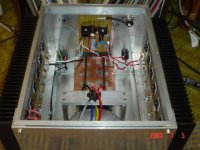
Like most of us my box ended up a little cramped, But if I made the change I would stack two transformers somehow on top of each other, probably 400 va with huge cores each rated to give 23 volts after rectification and filtering. The hard work is already done, the thing is I really love this amp.
Ian
Ian
Attachments
Depends. CLC has less loss (usually) and a sharper filter slope,nobody special said:I don't really understand why everyone wants to go CRCRC...
Dosen't an inductor (pi filter) do a better job of filtering?
Steve
but CRC has a more "passive" non-resonant non-magnetic
character, and with big caps can still do a good job. Ideally we
try both types out and see which suits best.
😎
Nelson Pass said:
Depends. CLC has less loss (usually) and a sharper filter slope,
but CRC has a more "passive" non-resonant non-magnetic
character, and with big caps can still do a good job. Ideally we
try both types out and see which suits best.
😎
CRC also takes less place
Nelson Pass said:
Ideally we try both types out and see which suits best.
Which is neither, that's why NP has chosen a CTC arrangement. A thermistor helps to limit the turn on transient current, comes in a small, heavy duty package that doesn't require much attention in terms of cooling and probably has better thermal properties than a WW resistor.
The fact that Nelson had those around in the shop must have played a significant role.
A New Idea
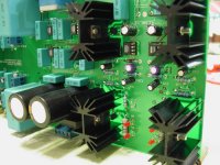
I am not yet shore if I want to build the a75, Aleph, or Aleph x. But I do have an idea as to how I want to build the output stage. The a75 uses 24 mosfets (12 per rail) for the output stage. The amp dissipates 164 watts to get 75 watts in class A. However each mosfet only dissipates 7 - 9 watts. That’s not bad at all. As I was looking over the passdiy gallery I noted that one of the builders (Pablo Torío) of the A75 used to- 220 mosfets in his amp, in a PDF he published about it. If we use to-220 dissipating 7 watts each we can use Digi-Key part number HS276-ND heat sinks. These heat sinks are rated 2.5 C / Watt and cost $1.25 10+. Each heat sink would be 18.75C above room temp. So if you wanted to dissipate 140watts you could use (5 heat sink preside per rail) 20 heat sinks in all at a cost of $25. That’s not bad. And best of all no drilling and threading heat sinks. The mosfets cost about the same. And even better you don’t need to use a washer between the mosfet and the heat sink because each mosfet is separate. And if you want a bigger amp just add more heat sinks. I think a big board like the AX amps have, with these heat sinks running down each side would be very sexy. Below is a pick of the heat sink I am talking about.
I know someone is going to say “but there not thermally coupled”. The A75’s output stage was not thermally coupled and buying a really long heat sink and putting the + output stage all the way on one side and the – output stage all the way on the other is not thermally coupled.
Maybe Mr. Pass can use this idea in his push-pull Zen v5. It would be really cool if Zen v5 when into class b when it runs out of steam in class a.
I hope this post is not too off topic, but we are talking about adding more mosfet per rail right?
Attachments
Nelson Pass said:
Depends. CLC has less loss (usually) and a sharper filter slope,
but CRC has a more "passive" non-resonant non-magnetic
character, and with big caps can still do a good job. Ideally we
try both types out and see which suits best.
😎
So, it's a matter of preferences then. Does the resonance create problems with a class A amp? I wish I had the voltage to spare to try the CRC. If Nelson likes it, that's a good sign that it will sound good...

- Status
- Not open for further replies.
- Home
- Amplifiers
- Pass Labs
- Aleph-X: High-Power Version