At the request of a member I am making some Aleph boards. I have decided to make additional sets and offer them.
The boards will be available next week. Each set will consist of 4 output boards, 2 rectifier boards and 2 input/driver boards. The rectifier and output boards are 3 oz. copper. The input/driver board is 1 oz. copper. The boards will be unplated and unscreened. I will drill for the common components such as the metal film resistors, caps, fets, rectifiers and output devices. Potential differences in transformers and wiring suggests that anyone ordering should either drill the remaining holes or supply me with hole sizes.
I have made some minor modifications of the rectifier and output boards, widening traces. GIF's of the traces on the rectifier and output boards can be seen at:
www.kbacoustics.com/aleph.html
Rectifier boards are $35 for a set of 2.
Output boards are $35 for a set of 4.
Input/Driver boards are $35 for a set of 2.
Full sets (8 boards) are $95.
Postage $4
Can someone please clue me on the the difference between the Aleph versions?
Note that I also do custom boards and small run work. Turnaround time could be as little as a week, depending.
If you haven't already done so, email with your needs.
programs@kbacoustics.com
Credits to NP and "not for profit" seem to be missing from the boards.
Oh, no silkscreen, I get it. Still, something along those lines might be something to consider.
Oh, no silkscreen, I get it. Still, something along those lines might be something to consider.
hi,
Quote:
"Can someone please clue me on the the difference between the Aleph versions?"
I don't understand that someone can design and then sell the PCBs and not know the difference amoung them.
Also, did you tested all the Pcbs in the operation ?
Correct me if I wrong, but on the your PCBs I see a couple of serious errors !
Attachments
I'm sorry I got into all this. I was browsing the Pass forum and noticed a need for boards and a lot of moaning and groaning about PC layout software and other difficulties. A pdf file containing the layouts was posted by BrianGT. So, I figured I can use the file as a guide, make the layouts a little better and offer the boards. Everyone's happy. Making boards is not really a big deal.
I thought these board layouts were already tested. I don't really know who did the layouts to begin with - at first I thought it was BrianGT then the name Wayne shows up and then kristijan-k has boards but they are different. Then there is talk of schematics being wrong and layouts having errors and some stuff on where C9 and the LED gets connected. No, they go here - no, they go there - no, it doesn't matter. . . .
If you have the layouts and a knowledge of electronics you really don't need a schematic to do new artwork for boards.
As an observation, I think the Aleph project threads are extremely un-orgainized. Nature of the forum beast possibly. Anyway, I don't think I'm going to make boards available after all. The whole thing is enough to give one a headache. I can't even imagine the turmoil a newbie has to go through to build one of these things.
Why isn't there a Aleph Clone website where the whole deal is laid out?
strobo said:hi,
Correct me if I wrong, but on the your PCBs I see a couple of serious errors !
Correct me, if I'm wrong, but i don't see any seriousness in that error. Somebody tries to help you out by making boards available and you already start to citisize. I think that not silkscreened boards sound better. If you don't like them, just don't buy them.😉
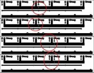
Strobo: Can you clarify exactly what is the error? Your circles around those areas doesn't tells me much. Please describe the serious errors. Thanks.
hi,
On the Bill Fitzpatrick PCB, I see the errors in the connections of the gates resistors with the some other resistor that is connected to the FET source.
According to the schematics I think that they are wrongly connected.
Also, at http://web.vip.hr/pcb-design.vip I founded the similar PCB, so I connected all the parts acordingly to the Pass schematics.
If that can help to someone, here it is:
Attachments

Strobo: You made a bold claim that the layout has some serious errors but you can't prove it. Instead you show us somebody else layout which (at least to me) looks exactly like what Bill has posted. The only difference is the location of the 4 holes for the hard wiring from the output board to the main board. So, once again, could you specifically point out to us what/where is the error!

After all I wasn't right. These are holes for connecting wires for sensing circuits. Strobo, both boards you presented here are correct, it just that the wires on first one are taken from the position in the center and on the other from the side. Now I start to be sorry I got into all this.🙄
Hello there,
The fcel and HPotter are right.
I also believe that the output PCBs of the Bill Fizpatrick are without errors and that they should work without any problems.
To the amateur, the PCBs can really look like that they have somes aditoinal resistors, but they really don't have them.
It's depends from what perspective you look at the PCB.
The areas on the PCBs that's look like the spaces for the aditional resistors are infact the terminals for the Sense and Gate wires.
At least at the mine opinion.
Warm regards,
Kristijan Kljucaric
It looks just like W. Sankey's PCB without the 45 degree angles at the end devices. <br> Sankey had the connections in the rear 2/3's or so of the PCB rather than the very end edge.
http://www.passdiy.com/gallery/aleph2-p1.htm
His PCB artwork is the last image link on the right.
http://www.passdiy.com/gallery/aleph2-p1.htm
His PCB artwork is the last image link on the right.
- Status
- Not open for further replies.
- Home
- Amplifiers
- Pass Labs
- Aleph PC Boards Available