Stefanoo said:so i hope you guys will be willing to hlp a noobies as me.
i would appreciate it very much.
Thanks iin advance for your support.
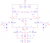
Aleph P1.7 schematic keeps the rule.
The four lines meeting at one point means not connected.
Only the three lines meeting at one point is connected.
If you don't mind my comment . . . stop bla bla bla, and build one.
There would be hundred lessons in one failure.

no, don't worry...i don't miind your comment.
It's that i would like to build this project from the beginning till the end and so starting from the correct simulation, passing through the layout and the simulation of the lay board...optimization of the layout board...and finally building the project.
But until i won't get the correct result on the simulated behaviour, i might won't build the board.
I would just love that somebody of the experted guy here on the forum would help me to understand why my simulation is failing.
That's all.
Stefanoo said:...optimization of the layout board...
Plz don't try to optimise at potential cost of buzzz and hummm.
And, don't forget doing failure mode analysis for total safety.
yes, i will...as soon i will have figured out the reason of why passing the schematic to the simulator i have that error that forbiddens me to see the results.
Need helppppp


Need helppppp
I don't have much experience with simulators but when they start crashing i would simplify the circuit as much as possible until something works. In this particular case i'd replace the CCSs with resistors and see how it goes.
I don't know what's wrong!!
Is there any experted guy there that is navigated with Orcad Capture and PSpice and can help me out with this simulation?
My Circuit is attached on the previous page.
It would be great, because i' ve gotten totallyy stucked and i don't know what else to do!
heeeeellllppppppp pleeaseeee.... 
Is there any experted guy there that is navigated with Orcad Capture and PSpice and can help me out with this simulation?
My Circuit is attached on the previous page.
It would be great, because i' ve gotten totallyy stucked and i don't know what else to do!
heeeeellllppppppp pleeaseeee....
Stefanoo said:I don't know what's wrong!!
R6 & R9 (on your schematic) should not be connected to the signal inputs. These resistors are for allowing a few mA of current to flow so that the top and bottom current sources turn on.
Stefanoo said:But until i won't get the correct result on the simulated behaviour, i might won't build the board.
I would bet good money that Nelson's circuit works just fine without simulating 😉
Stefanoo, I am by no means an expert and I typically use schematics for pspice instead of capture. It's easier😀 I typically check the "Bias Point detail" box and the "Transient" option. In the Transient option I check the "Detailed Bias Point" box and the "Enable Fourier" box. I typically start out with a 1kHz sine (from the Vsin component) so I will use a 10ns "Print Step" and a 100ns "Step Ceiling". In the Fourier option I naturally put "1000"Hz, "10" Harmonics and my output variable...
I have a circuit that is based on Nelson's BZLS and the 1.7. It sims just fine...
😀
I have a circuit that is based on Nelson's BZLS and the 1.7. It sims just fine...
😀
That's what i do.
With capture i select first the bias point calculation (eather way it does this calculation anyway), and i check the "detailed bias point information" checkbox and then run the analysis.
The problem is, that it doesn't allow me to go forward because it says:
ERROR -- Convergence problem in bias point calculation
These voltages failed to converge:
(ist of the not convergent voltages)
i don't know if anybody may analyze my files with schematic or not.
Pleaseeee...helpppp
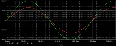
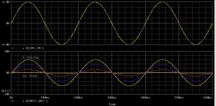
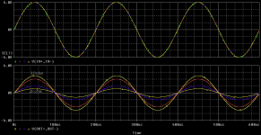
this is the analysis by varying the trimmer for a 1K output potentiometer..
I don't understand one thing.....
This design already has the input regulation by mean the input divider resisor, setting propertly the switches.
why is there a trimmer?
Is it not pointless? may somebody clear this up?
I don't understand one thing.....
This design already has the input regulation by mean the input divider resisor, setting propertly the switches.
why is there a trimmer?
Is it not pointless? may somebody clear this up?
Attachments
Stefanoo said:this is the analysis by varying the trimmer for a 1K output potentiometer..
I don't understand one thing.....
This design already has the input regulation by mean the input divider resisor, setting propertly the switches.
why is there a trimmer?
Is it not pointless? may somebody clear this up?
The trimmer sets the gain for both channels to be equal. Remember, it's a zero overall feedback circuit and the gain is dependent upon the mosfets parameters.
NP mentions that one can control the volume using a variable resistor in this position. It sounds like a really attractive proposition as a single pot effectively replaces two highly matched ones.
Only it doesn't seem to work that well in practice. You can't get the volume down to zero, you get a weird control characteristic and volume dependent distortion.
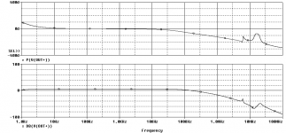
Stefanoo said:finally the frequency response..
is it ok to have that that peaks at around 10MHz? COuld it be a problem for the autooscillations?
Is the simulated behaviour ok for you guys?
Could you please explain what is your vertical axis? One seems to be degrees; how many db per division for the other?
Interesting results. In another thread i mentioned my 1.7 oscillating around 10MHz until i increased the grid stoppers.
Stefanoo, glad to see you got your sim running all the way through 😀 A convergence problem is a typical type of error. Ussually they are due to high gain or oscilation or something a little bit wrong somewhere. When you get the window that allows you to change some parameters, I ussually lower the current resolution a couple decades(I think thats right, go down to E-9 or 6) and the sim will go all the way through...
I believe my pre has a little bump starting at 750kHz or so (in reality) but those are the sorts of things that a real circuit may differ from a simmed circuit on.
You may sense a little anomosity towards the simulation philosophy But many of the people here are either of the objective or subjective camps and it is an endless debate of measurement or listening performance 
Everything that comes from Nelson Pass is worth listening too! THD and sim results are not the eqiuivalent of listening. They are just a tool to help evaluate with equipment and computors. Listening is the ultimate performance measurement 😀
I have included a pic of my Pass "variation" pre for you and everyone to comment on, or build, if you like 😀 😀 😀
I believe my pre has a little bump starting at 750kHz or so (in reality) but those are the sorts of things that a real circuit may differ from a simmed circuit on.
You may sense a little anomosity towards the simulation philosophy
But many of the people here are either of the objective or subjective camps and it is an endless debate of measurement or listening performance Everything that comes from Nelson Pass is worth listening too! THD and sim results are not the eqiuivalent of listening. They are just a tool to help evaluate with equipment and computors. Listening is the ultimate performance measurement 😀
I have included a pic of my Pass "variation" pre for you and everyone to comment on, or build, if you like 😀 😀 😀
Attachments
I used to simulate once in a blue moon until I tried to simulate a circuit that I already had working. It said it wouldn't work. My skepticism was cemented later on when I started the Aleph-X thread and was told by those who treat simulations as Revealed Truth that the circuit would not, could not, under any circumstances, ever, work. I knew differently because I had a functioning prototype at my elbow.
I regard simulations as a waste of time that--at least for me--would be far better spent trying real circuits on the bench. And...for those who live in fear...I popped a MOSFET and a resistor a couple weeks ago. Total cost of the two was about a buck. First time I've blown anything in ages. Incidentally, it was my fault for letting two wires touch. The circuit design was just peachy, albeit somewhat lower bandwidth that I'd been hoping for. And I know the results I obtained are good, because they were based on real parts in the real world, not incomplete models of "perfect" parts.
Or, in the vernacular: Reality beats theory, seven days a week.
The sad thing is that for all the time and angst wasted on this simulation thing, the preamp could already have been built. I have yet to hear music reproduced by a simulation...
Although I have no doubt that someone, somewhere is writing the code for such a program.
Grey
Yup, I agree. It may be mostly due to lack of interest in learning yet another type of software, but I can knock out a board design in Eagle, burn the PCBs with toner transfer, and have something up and running pretty quickly, so why even bother with sims?
I bother with it...first it helps me understand how a circuit works and not how it sounds...that's second.
flg,
Nice iteration.
At least for me there are some undefine areas on the schematic, like were you connect the attenuator, Gain pot? Bias?
Could we have some details on these?
and the most important Q, how does it sound? Compared to P 1.7?
P.D. This could well be a new thread.
Nice iteration.
At least for me there are some undefine areas on the schematic, like were you connect the attenuator, Gain pot? Bias?
Could we have some details on these?
and the most important Q, how does it sound? Compared to P 1.7?
P.D. This could well be a new thread.
- Status
- Not open for further replies.
- Home
- Amplifiers
- Pass Labs
- Aleph P1.7 "the design starts here"