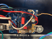
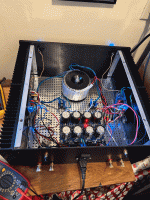
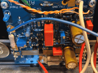
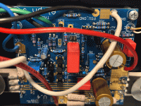
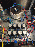
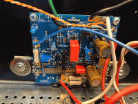
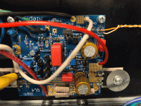
I recently built the Aleph JZM. I have tested it and I'm getting 450mV at r29 on both channels. My offsets at the speaker terminals are as close to 10mV as I could get them but they really fluctuate a lot. On the right channel, I accidentally scraped off the pads on R27 where it's super close to one of the legs of the MOSFET. I ended up soldering the resistor to the leg bc I assumed that's where it wants to connect to?
I'm getting a ton of distortion in both channels but particularly in the right channel. Also, I've seen the dreaded white smoke a couple of times and I'm not sure where it came from on the boards. Both GBR resistors look lightly toasted.
Can you guys please help me to diagnose what's going on? Please be gentle, this is my first real intermediate build and I still am quite a beginner. Thanks
-Adam
Attachments
dunno for GBR, have no ideo from pics, but - when using SE (RCA) input, you need to short -IN to GND (instead of leaving it floating)
there is a JP1 for exact purpose, and even a note "short for SE in"
that can cause distorted sound in your case, same as some fluctuation of output DC OFfset, in general
though, 10mV is practically nothing, and your definition of fluctuation needs to be described in detail - illustrated with some numbers - how much and how fast
replace both GBRs with 0R resistor - short piece of wire - they are toasted and who knows in what state they are, regarding resistance
Also, just noticed in my pictures that at JP 1 it says to short for SE inputs. I am only using SE inputs and I've misplaced the shorting caps
ok, I just bought some jumper caps on amazon since I misplaced the ones from the kit. Hopefully that'll get me on the right track
Or if you have an ACA mini kit, the kit has jumpers. Hopefully you sort it out! Amp is incredible!
Don't laugh but if you have old dead computers you can salvage a lot of jumpers from the motherboards; that's where I got my spare jumpers from. 🙂
Hopefully you will get this sorted out soon.
Dennis
Hopefully you will get this sorted out soon.
Dennis
Haha, just bend the pins together with pliers and put a touch of solder to connect.
This is surely due to MZM’s recklesness. The schematics must include a disclaimer about all parts having to be installed.
Though, the white smoke is bad news. Perhaps a few real closeup pictures of the front and back of the boards would be handy, if shorting -in to gnd doesn’t do the trick.
Though, the white smoke is bad news. Perhaps a few real closeup pictures of the front and back of the boards would be handy, if shorting -in to gnd doesn’t do the trick.
In all honesty AlephJzm build guide is the most detailed over the top step by step guide ever. Period.
I was just joking, Adason. Always trying to tease the mighty one. My boards don’t have jumpers, but the blueprint is very clear about the need to ahort those points if going SE.
The amp is now performing wonderfully. I shorted -IN to IN ground using a wire and I re-soldered some of my suspect joints. My lq pot wasn't working on one channel, but after the re-solder it's back in business. I recalibrated the bias and the offset and now it's sounding wonderful. I actually found the jumpers. I was considering putting them on and taking the shorting wire away but they just fall off the pegs if you move the amp at all. Am I supposed to crimp them? I figured it's working now so don't mess with it. Is there any advantage to using jp1 to short as opposed to using a wire?
Is there any advantage to using jp1 to short as opposed to using a wire?
no; especially if that jumper is so botched, so it falls off while moving the amp
or you're especially rough, while moving ?

I loaned Adam my 500 pound anvil last week.... came back so mangled I couldn't believe it!! (j/k Adam 😀 )or you're especially rough, while moving ?

- Home
- Amplifiers
- Pass Labs
- Aleph JZM troubleshooting
