@birdbox Thanks for pointing this out. To try to make sure I was doing it correctly, I sketched out the correct view of the board (left) and then the "flipped" version (right). I changed my setup on the flipped (240V) to match the sketch in the attached photo. It turns out the silkscreen labels seem correct either way - with the neutrals (white for me) lined up with the 0A/0B (black for me) and the hots/line (blue for me) lined up with the 120A/120B (red for me). Note that in the photo, the top board is the incorrect 240V showing and the bottom is the correct 120V showing and I now corrected the wires based on your comment. I think this is now good to go.
Please let me know if I got anything wrong here. My next step is to clean up the remaining wiring and then plug it in to a dim bulb and measure.
Thanks again for everyone's input.
Jim.


Please let me know if I got anything wrong here. My next step is to clean up the remaining wiring and then plug it in to a dim bulb and measure.
Thanks again for everyone's input.
Jim.
Hey there all,
I plugged her in today. Flipped the switch of the dim bulb tester (DBT), 100W lightbulb lit then quickly dimmed off. However, only one LED on one of the boards lit (the left one lit) - so I shut the DBT switch off, unplugged everything and I am leaving it alone until tomorrow. No smoke or sounds or anything noticeable to report. The LED that lit stayed on for a while after unplugging and is now off. I took some photos before I plugged it in.
1. Are there any measurements that I can take to troubleshoot with it off?
2. Since the DBT didn't go on, am I free to measure stuff next time I try to plug it in?
One thing I will check tomorrow is the fuse mounted on the board. The fuses holders were a bit janky and I will make sure that all of the connections are okay. I am also going to unplug and replug-in all of the quick connects on the boards and snubbers.
Let me know if you have any troubleshooting advice. Thanks in advance.
Jim.
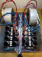
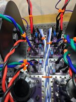
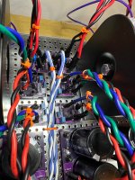
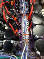
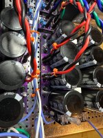
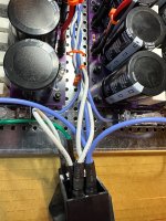


expect more help from Boyz being familiar with those pcbs
much better than letting me doing guesswork
much better than letting me doing guesswork
@rhthatcher Here's some photos of the board that doesn't work. Please let me know what you think.
Thanks.
Jim.
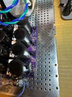
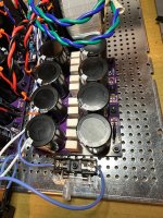
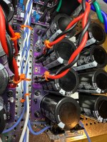
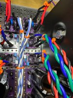
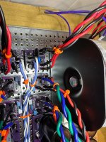
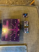
Thanks.
Jim.


Last edited:
Let’s take this in steps.
Pull the good channel fuse for now so we can focus on the non working channel.
If you pull the wires that connect the rectifier to the V8 board you can test that we get juice though fuses, cl60 board, donut, and to bridges. So you’ll want to use your dmm to measure DC voltage at each bridge. Do you have some clip type probes?
If you get 24ish volts at the bridges we can then look at hooking up the v8 board. If not, we need to look upstream of the bridges.
@rhthatcher Got it. So pull both sets of wires that are circled in green in the attached photos and attach a DMM probe to each wire, one set at a time? Or pull those same wires directly from the rectifier bridges and measure directly from the bridges? (Probably works either way?) Does it matter how I hook up the DMM? Just one probe to + and one to -?
Thanks.
Jim.
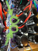
Thanks.
Jim.

Pull from both bridges. You don’t want any voltage hitting the board.
You can pull at the board side or the bridge side of the wires. And measure voltage of each pair. Make sure that you don’t have a live pair of wires flopping around and potentially touching the chassis. Maybe wrap the pair you’re not measuring in a bit of a electrical tape
You can pull at the board side or the bridge side of the wires. And measure voltage of each pair. Make sure that you don’t have a live pair of wires flopping around and potentially touching the chassis. Maybe wrap the pair you’re not measuring in a bit of a electrical tape
Hey there,
Thanks @rhthatcher and @Zen Mod for the notes. And special thanks to @birdbox who talked thru troubleshooting with me on the horn and solved it - it was the fuse holder! Ha! When we pulled the top portion of the fuse holder and replaced it with a just a fuse, I got +/-23.6V on each of the outputs and LED shining brightly. Thanks again all! On to the rest of the Aleph Jzm!
Sincerely appreciate all of the help from this community.
Jim.
Last edited:
Hi,
Now that everything seems to be working, laying out other needs just as a reference for others going down this path of building a power supply unit for the first time:
Happy building. Cheers, Jim.
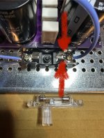
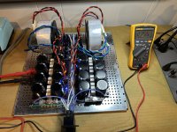
Now that everything seems to be working, laying out other needs just as a reference for others going down this path of building a power supply unit for the first time:
- The fuse holder fix consisted of squeezing the fuse holder tabs a bit to tighten them up. Shown in Photo 1.
- Here is a list of most the stuff I needed to complete the power supply unit build. Though most of this stuff is probably already in the toolboxes of more experienced folks. Also, there are many ways to accomplish some of the tasks to build the PSU's, but this is how I went about it. I did rely pretty heavily on Amazon. Not happy about that, but it is what it is.
- Back Panel Kit from diyaudio Store. Currently sold out but seems to be restocked often. Back Panel Kit
- Heat shrink - I bought an assortment, and still had a bunch from a previous build.
- Fuse Holder - I took off the bottom part and mounted them to the chassis with screws and nuts. I also had to squeeze the tabs as noted above and in the photo. Fuse Holder I know that some folks like to have the fuses accessible form the outside, but I did not want to drill into the back panel.
- Fuses - you need to figure out the correct fuses for your transformer. Mine are based on a 200V transformer. For the fuse holder shown above and for my transformer I used these 6mmx30mm 1.6A 250V Slow Burn Fuses. These are the fuses that are supposed to be in the back panel kit, but mine came with two 10Amp fuses instead of one 10Amp and one 3Amp. 5mmX20mm 250V Slow Burn Assortment
- Quick Connects and Crimp Tool - I actually cut the heat shrink off these after I crimped them to the wire so I could solder the wire to the crimped connection and then used my own heat shrink. (Probably unnecessary but I am anal retentive.) Connectors and Crimp Tool I felt the build quality of the connectors seemed pretty good. These worked well with the spades that were in the PSU build guide parts list.
- Wire - duh, but I didn't have much laying around. This Wire is pretty nice to work with.
- Nylon spacers for keeping PCB's apart from the chassis. Spacers
- Screws, Nuts, Washers. I used 4mm, but they were a little tight in some of the perforations. Worked fine in the end, but could also consider 3mm. Hardware Note that the order should be screw, washer, connecting parts, washer, lock washer, nut.
- Thermal Paste for the Rectifier Bridges to Chassis interface. Just smear it on evenly. Paste
- Transformers - I used these AnTek ones, but you can go a bunch of different directions here. Transformers
- Transformer Mounting Brackets - you may not even need these depending on the size of your chassis. These were made specifically for the transformers that I bought.
Happy building. Cheers, Jim.


Last edited:
Jim,
Great list! These the odd and ends that are needed for builds. I’m sure I’m not alone in buying the little kits that have enough parts for many builds - heatsink, bags of quick disconnects, fuse assortments, spacers, etc.
Now that you have all the extra goodies in your stash - what are the next few amps on your agenda?

Did the Etsy Thatcher PSU (https://www.etsy.com/listing/143163...431637388&click_sum=79ffaefd&ref=user_profile) get replaced with something else? It doesn't seem to exist anymore. I've tried searching this thread for any sort of references to it no longer being available, but I haven't found anything.
It’s temporarily out of stock, and will be coming to a familiar store soon.
If this shows up where I think it's going to show up, it's going to be a very popular item and well received by the diy community! Awesome news!
- Home
- Amplifiers
- Pass Labs
- Aleph Jzm Thatcher / Etsy PSU Build and implementation discussion