Oil & Paper Capacitors
Hi,
I know it has been a few weeks since my last time here. Currently I have purchased a ballanced DAC with a class A amp insted of op-amp, and these pcb's use Russian Oil & Paper Capacitors, I am still working on my Aleph J-X mono amps so I am able to purchase the Russian Capacitors for C1 1uF, and the two capacitors I am using on my "Passive Line-Level 12db second order Crossover" of 0.15uF & 0.015uF respectively
http://www.ebay.ca/itm/220629588607?ssPageName=STRK:MESINDXX:IT&_trksid=p3984.m1436.l2649
dose anyone know anything about these, should I use them ?
Thank You
Ian
Hi,
Did you use three 5watt resistors ?
Thank You
Ian
sorry i didnt see your question, no i'm not using 3 sets of outputs, just 2, so just 2 x 5w for me per phase
useing 3 resistors
Hi,
I have decided to go with just one for the first amplifier build just to make shure the design is ok, I will never know untill I am finished building it. On the next one I will put in the three resistors if the 3watt dose not seem to be strong enough for the amount of heat produced.
Now I am ordering some Russian oil & paper caps for my 12db per octive high pass "Passive Line-Level Crossover" at the amps input at 100Hz.
any comments on this
sorry i didnt see your question, no i'm not using 3 sets of outputs, just 2, so just 2 x 5w for me per phase
Hi,
I have decided to go with just one for the first amplifier build just to make shure the design is ok, I will never know untill I am finished building it. On the next one I will put in the three resistors if the 3watt dose not seem to be strong enough for the amount of heat produced.
Now I am ordering some Russian oil & paper caps for my 12db per octive high pass "Passive Line-Level Crossover" at the amps input at 100Hz.
any comments on this
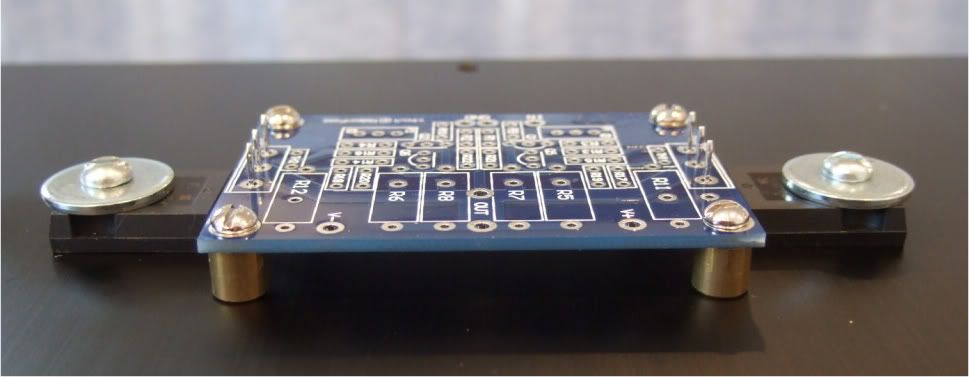
Can anybody help me out with a "mounting hole specification" for the aleph jx? I looked here but I didn't find anything, and the boards I don't have here.
What would you prefer, to only mount the boards indirectly with the transistors, or to mount both, transistors and boards? Is there a drilling layout for the transistors?
Kind regards,
Matthias
What would you prefer, to only mount the boards indirectly with the transistors, or to mount both, transistors and boards? Is there a drilling layout for the transistors?
Kind regards,
Matthias
Last edited:
The mounting depends on which PCB you use.
And, as you said, you could mount the PCB only with the transistors.
And, as you said, you could mount the PCB only with the transistors.
Ok, you'd prefer both possibilities.
And do you also know the spacing for the holes to mount the transistors?
And do you also know the spacing for the holes to mount the transistors?
That depends on how much lead you have on the transistors before the 90deg bend. You are going to have to get a TO-247 package device and measure, the add it to the spacing of the PCB
My plan is to get the holes cnc drilled, so i need the measures before i solder the big transistors. For this the distance between the board and each transistor has a few millimeters tolerance, but not the distance between the transistors.
Your PCB are similar to these - yes?
The distance between the transistors in the vertical dimension is the same as the middle hole of the transistor's solder pad. (Where the middle pin attaches)
The distance in the horizontal dimension is ultimately decided by the location of the 90deg bend in the transistor's legs.
The distance between the transistors in the vertical dimension is the same as the middle hole of the transistor's solder pad. (Where the middle pin attaches)
The distance in the horizontal dimension is ultimately decided by the location of the 90deg bend in the transistor's legs.
Last edited:
Greetings friends,
I'd like any suggestions on a general plan of attack to get my Aleph J boards running and playing. The project got off to a good enough start in that I made a nice silent fan+heatsink+chassis that should serve well. But things got dicey when I made a mistake and sourced fake J74s in the front end. Some heat damage occurred and then, step-by-misstep, it was all downhill... power diodes began to snap - ugly. I walked away from the project.
Now, some months later, I have stored up enough patience to work on it again. I don't really know which of the installed active components to trust. Obviously I'm NOT overqualified for this project, though I enjoy learning! 😛 Any helpful hints on a plan of attack? I was thinking of just replacing all of the fets as a start. But how about the passive components? Any and all suggestions much appreciated.
Frank
Any helpful hints on a plan of attack?
101 : check everything before you start.
102 : make a strategy plan
103 : check again.
Tip : with a few formulas and a 5 dollar DMM, every active/passive component can be checked and/or value guesstimated. Resistors, BJTs, JFETs, also capacitors.
(at least you've got first base covered : modesty. For an example of the effects of arrogance, see Pumpkin thread)
(at least you've got first base covered : modesty. For an example of the effects of arrogance, see Pumpkin thread)
LOOL
...will check out that thread... thanks Jacco - I'm particularly puzzled by what happened with my power supply diodes. Any reason NOT to bring this beast up to power gradually through the Variac?
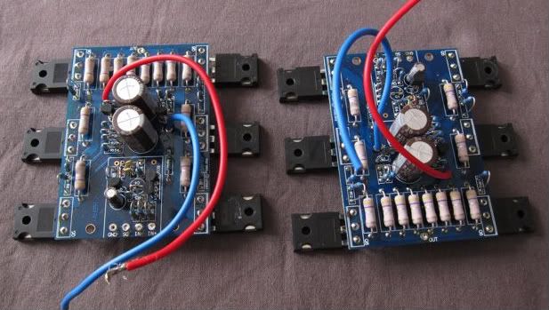
PCB Front End Population
Hi Everyone,
I am finally populating my pcb(s) and have run into a problem, there is a place for two transistors, J74 & Q2, according to the schematic I have only one of these should be populated, similarly with the two P1 & RP laid out on the Front End pcb ?
On the schematic there are two resistors boxed off at the bottom connecting to Volts negitive, and there is a note that says "on output boards" what resistor number corresponds to these resistors ?
My amplifier nears completeion once I have resolved these issues stated here.
Thank You For Your Help
Ian Scaiff
gaseclabs@rogers.com
For clarity purpose I'm attaching front end schematic here.
The circuit in the top left corner marked as Alternate Current Source was suggested by EUVL. You can either use it or stay with original Aleph current source based on Q2. In case of a latter, just don't install RP, P1 and J74 on front end board. And that's what I would suggest initially. After you have your amp working and tested, you can start experimenting with alternative circuit.
The two resistors connecting to V- and marked "on output boards" are simply R7, which are located on main boards. In case of AJ-X you will have two of them (one per each output board).
Attachments
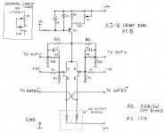
J74 current source
Hi,
I have the J74(s) for the current source, do I just omit the Q2, RP, P1 grouped together near the Q2, and populate the J74, RP, P1 grouped together near the J74.
Thank You For Your help
When I get the two channels working I will be building two more mono Aleph J-X for 5.1 movies surround sound.
For clarity purpose I'm attaching front end schematic here.
The circuit in the top left corner marked as Alternate Current Source was suggested by EUVL. You can either use it or stay with original Aleph current source based on Q2. In case of a latter, just don't install RP, P1 and J74 on front end board. And that's what I would suggest initially. After you have your amp working and tested, you can start experimenting with alternative circuit.
The two resistors connecting to V- and marked "on output boards" are simply R7, which are located on main boards. In case of AJ-X you will have two of them (one per each output board).
Hi,
I have the J74(s) for the current source, do I just omit the Q2, RP, P1 grouped together near the Q2, and populate the J74, RP, P1 grouped together near the J74.
Thank You For Your help
When I get the two channels working I will be building two more mono Aleph J-X for 5.1 movies surround sound.
Heatsinking
I have just finished reading 128 pages of this thread and have found a lot of comments about adequacy of heatsinking for this amp. Many have said that massive heatsinking is required. My problem is to put this into perspective.
I realise the heatsinking for a 100W Aleph J-X monoblock is going to be large, but assume it is no larger than required for an Aleph 2 (100W monoblock)? Am I right to assume this?
If so, can I suggest the 4U 400mm modushop (e.g. 1NPDA04400N) cases? modushop.biz
I have a pair of Aleph 2 monoblocks in these cases and, while they run hot (sorry, no thermometer) they have survived for over 5 years.
The technical details of the heatsinks (4 x 3PD04200 in each case) can be found here: modushop.biz
The cases use 4 heatsinks each, resulting in a temp. coeff. of < 0.1C/W.
I realise these are not cheap, but they are well made and have served me well. There are slightly cheaper versions of the case (with steel top, bottom and rear).
I do realise these are probably not the best choice for people outside the EU due to high shipping costs.
The J-X has twice the number of output and current source transistors than an equal powered Aleph. So you will need more heatsink.
It seems logical to choose the 5U by 400mm, as it has the same footprint and the 4U.
Remember, Nelson himself has always said that you can't have heatsinks too big.
It seems logical to choose the 5U by 400mm, as it has the same footprint and the 4U.
Remember, Nelson himself has always said that you can't have heatsinks too big.
- Home
- Amplifiers
- Pass Labs
- Aleph J-X Amp Project