Hi everyone,
I just finished an Aleph J build and fired it up yesterday. I previously built an F5 without issue.
The power supply and one channel are working great. I'm getting 24.5W+ and 24.5W-.
On the other channel, I had smoke from R17 and R19, and Q8 and Q6 died. I thought maybe they were touching the chassis, but after looking at it closely, I'm 90% sure they were not. I'm using the Keratherm patches and there don't appear to be any holes or scoring, which I have seen in the past if there is inadvertent contact.
I built the two Aleph J boards together using identical parts and have compared them and found no differences.
I did find a bad solder joint on C7 on the bad board, but I am not convinced that is what caused this problem.
In terms of testing, I've checked Q4, Q5, and Q7, and all are fine. Haven't tested Q2 or Q3 yet, but can do so if there is any change they could be the problem. Also haven't tested the JFets yet.
I used Dale resistors and checked each before installing.
Based on the schematic, does anyone have any ideas of the potential cause or what to test next?
Could a short at the speaker terminals or rca input have caused this?
Any thoughts greatly appreciated.
Please provide a copy of the schematic you used so that we know what you are referring to by R17, R19, Q6, Q8, etc.
Also, please use a DVM to confirm if the output devices are properly isolated from the chassis.
Also, please use a DVM to confirm if the output devices are properly isolated from the chassis.
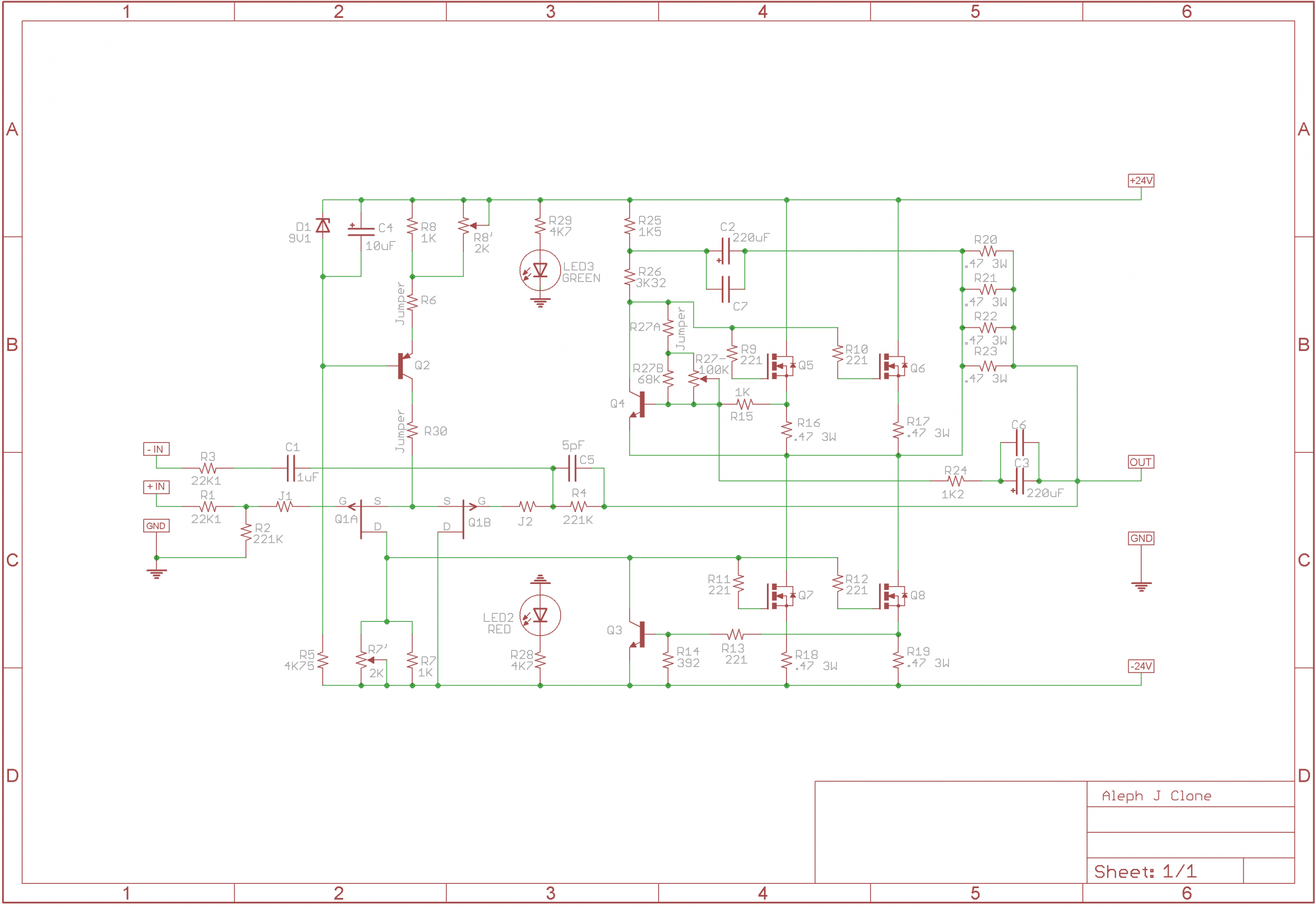
As mbrennwa said I would guess Q6 and or 8 were shorted to the heat sink.
You should build a light bulb current limiter for initial start up. It can save some headaches and burnt parts
You should build a light bulb current limiter for initial start up. It can save some headaches and burnt parts
Before doing much, I'd remove the broken parts Q6 and Q8. Make sure the inputs are shorted to GND, and the speaker output is not shorted. Then turn on the amp again (with a bulb tester, if you have one). If there is no more smoke or funny smells, measure the voltages across R16 and R18 and report back.
Okay, something is definitely wrong.
I reinstalled new components and made 100% sure no contact between outputs and chassis.
Here is the issue. For R16 and R18, the bias is normal on start up and stable around .5 volts (without any adjustment at all)
For R17 and R19, the bias starts out in that range, but then continues to rise quickly. I have been unplugging it when the bias gets to about .9v for fear of frying the amp.
Any ideas appreciated.
Check the pins on Q5 and Q8 for continuity to ground. All 6 pins should not show any continuity. Most multimeters have a buzz feature when checking for continuity. Most likely one of the pins is grounded. If not check the voltages on the pins with the correct operating mosfets Q7 and Q9 and compare. Strange that one mosfet is in the output stage and the other in the CCS.
Did you check that the replacement Q6 and Q8 match Q5 and Q7? If not, it's possible
for the new Q6 and Q8 to turn on much faster than Q5 and Q7.
for the new Q6 and Q8 to turn on much faster than Q5 and Q7.
Stop poking around in the dark. Work in a systematic way to isolate the issue. How about post #5?
Okay, so I ended up replacing the trim pot at R27 with a 68k ohm resistor and swapping out all four Mosfets and it is working as it should. Stable at .55v or so. I will eventually swap out the resistor after I get a new one from Mouser.
But when I realized how stable all four mosfets are on this channel, I realized something funky was going on in the other channel. It is not melting down or anything, but the voltage on Q6 appears to bias properly at .55v and then slowly drop.
The voltage on Q8 also isn't stable, and seems to rise slowly, although I need to test it again when I have time later.
I triple checked to make sure the mosfets are not grounded to the chassis. Will try to run some other test tomorrow, but let me know if there are any specific voltages that would be helpful to help diagnos.
Thanks.
Pass DIY Addict
Joined 2000
Paid Member
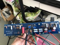
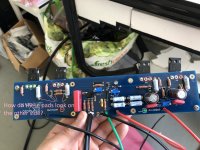
Solder joints on Q5, Q6, and Q8 look like cold solder joints. Reflow each with an appropriately hot iron and enough solder. Make them look like your solder joints on Q7 - these look nice.
Before mounting your mosfets, have a look at the the mounting holes on the sinks to make sure there is not a raised lip as a result of drilling/tapping the hole. Use your finger and swipe across the hole. It should feel smooth and level without a lip.
After mounting your mosfets, use your DMM and check for continuity between the center pin of each mosfet with the heat sink itself to check for an unwanted short. The center pin is connected to the metal tab on the back of the mosfet. There should be no connectivity here. I am no longer a fan of any kind of "sil-pad" because they pierce far too easily. Have a look for Aavid 4180G Aluminum Oxide Ceramic insulator. With a little heat sink grease, they outperform any silpad and NEVER puncture.
You should build a light bulb current limiter for initial start up. It can save some headaches and burnt parts
Couldn't agree more!
Pass DIY Addict
Joined 2000
Paid Member
Keeps smoke in the box. Hard to put back in once it is let out.
With the Aleph J the light will glow due to it's current draw but one should still be able to tell if everything is correct. I will assume you will still see some components changing color or starting to smoke if things are not correct.
With the Aleph J the light will glow due to it's current draw but one should still be able to tell if everything is correct. I will assume you will still see some components changing color or starting to smoke if things are not correct.
Okay, so taking the advice of those in this thread, I took a systematic approach and checked every part.
I first removed both Aleph J boards.
Then I removed all of the transistors, including the jfets. I then checked every remaining part, including the resistors and capacitors (both to make sure they measured correctly and to make sure they matched the schematic in the build thread). The zener diode on the channel that went REALLY bad (with 24V offset) was open and a few of the ZTX transistors were blown. The Jfets were also blown.
I then checked the power supply to make sure that it was stable at approximately 24V +/-. It is, right at 24.5V +/-. It also dimmed the bulb completely on my dim bulb tester with no channel attached.
I then replaced all of the transistors with brand new ones in one channel. The mosfets are from the same mouser batch and all measured with a Vgs of 3.22. I also replaced the two .47 ohm panasonic resistors that had burned out earlier.
I then reassembled one channel and made 100% sure no mosfets are touching the chassis. I used a multimeter to confirm no continuity.
I then started up with a dim bulb tester. The offset was about 2V, but I was able to adjust it down easily with the trim pot. The bulb didn't dim that much, but I understand from 6L6 earlier posts that this is not uncommon with this board and that if the offest is low you can try to start it up.
Did so and the bias seemed to start at the right point, around .58 v, but then started to be unstable and right as I unplugged it I saw a tiny puff of smoke, but couldn't tell exactly where on the board it came from.
I've done nothing since and am totally bummed. I built an F5 without issue, but this is incredibly frustrating. I have literally poured over the schematic, and checked every part multiple times.
Are there any specific measurements that I could post that could help someone diagnose what could possibly be the problem? I haven't started it up since.
Love this hobby, but it can be so frustrating (and expensive).
Thanks all.
Th
Last edited:
I'll have to echo Eric on that a lot of the solder joins look questionable:
Make sure every connection for every component looks like the smooth transition from pad to wire like on Q7 (green square) on at least one side of the board.
Also either I use way too much solder myself but I'm a little suspicious that when I look at the other components only rarely has the solder has gone through the pad holes to the other side. Makes me think that there might be cold solder joins there too.
Attachments
Last edited:
- Home
- Amplifiers
- Pass Labs
- Aleph J - Smoke on R17 and R19 - Two blown outputs