I haven't finished the service manual for publication, but it is
quite clear that many have become impatient.
www.passlabs.com/np/Aleph_J_sch.pdf
😎
quite clear that many have become impatient.
www.passlabs.com/np/Aleph_J_sch.pdf
😎
Attachments

Nelson Pass said:I haven't finished the service manual for publication, but it is
quite clear that many have become impatient.
www.passlabs.com/np/Aleph_J_sch.pdf
😎
not bad , Papa .............

Thanks Nelson!
Did you do comparisons with the CCS feeding the differential pair?
I have to say, I'm a bit surprised not to see a '9610.
JJ
Did you do comparisons with the CCS feeding the differential pair?
I have to say, I'm a bit surprised not to see a '9610.
JJ
4 hours from first post and just 42 downloads...........
seems that greedy boyz around the globe are sleepy

seems that greedy boyz around the globe are sleepy
Hello
The direct download of the attachment from the diyaudio forum was so slow that I did go to the pass lab web site at; http://www.passlabs.com/np/Aleph_J_sch.pdf ,and that link work good for me.
Maby it's why there is only 42 download, but I'm maby the only one who have that download problem.
Now I have the schematic, thank m. Pass
Gaetan
Choky, did you think I missed it...?
Mr. Pass,
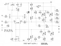
Aside from the jfet diff input with bjt ccs, looking at the output ccs...is R27 really between C and B of the voltage reference npn transistor (Q4)? Thanks for posting the circuit.
Mr. Pass,
Aside from the jfet diff input with bjt ccs, looking at the output ccs...is R27 really between C and B of the voltage reference npn transistor (Q4)? Thanks for posting the circuit.
pic for lazy boyz
hehehe
R27.........
that really doesn't matter
C2 is pretty good decouple even across R26
Blues said:Choky, did you think I missed it...?
Mr. Pass,
Aside from the jfet diff input with bjt ccs, looking at the output ccs...is R27 really between C and B of the voltage reference npn transistor (Q4)? Thanks for posting the circuit.
hehehe
R27.........
that really doesn't matter
C2 is pretty good decouple even across R26
Attachments
mpmarino said:Death of B
Zen,
that's it, pack your bags and move to Oz.
(Greedbags even more sleepy, I downloaded several times to different PC's in my network)
Thank you very much!
Cool a new toy for the weekend! Somebody already heating up Protel?
All the best, Mr. Impatient
Cool a new toy for the weekend! Somebody already heating up Protel?
All the best, Mr. Impatient
It seems that there aren't any major changes to the original Aleph circuit other than 2SJ109s with 1k drain resistors, and the Aleph current sensing resistors placed outside the global feedback loop.
Or I am still not fully awake ......
Patrick
Or I am still not fully awake ......
Patrick
First to say: Thanks a lot, Nelson!
After a quick look 2 questions raised:
Which type of 2SJ109 is the right one. With a current of 4 - 4.5 mA running through each of the FETs, the GR type seems to be inappropriate. BL and V should work in principle, but I lack the experience to decide which one would be the better choice.
Maybe not so important, but the current through LED1 seems to be very low.
Greetings,
Chris
- Home
- Amplifiers
- Pass Labs
- Aleph J Schematic