I also have a soft start and a speaker protection. But these were all by-passed when I test the amp.
same problem with both channels ?
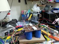
I can't see anything wrong , except fact that mosfets are way too high mounted on htsnk ...... but that's not problem seeing that you're having enormous heatsinking
using SE or balanced for listening test ?
if SE , don't forget to gnd neg input leg
I can't see anything wrong , except fact that mosfets are way too high mounted on htsnk ...... but that's not problem seeing that you're having enormous heatsinking
using SE or balanced for listening test ?
if SE , don't forget to gnd neg input leg
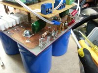
Goodness! Those are 47 ohm resistors! I spend hours and hours checking for loose joints, bad solder points...cleaning up the board, changing wires,etc. Now, I can't get any 0.47 3w resistors.....only 5w and these are too big for Peter's board. I'll use 0.5 ohm 3w resistors instead and the amp plays. The image shows the measurement after about 5 minutes of the amp playing. Is it okay to use these 0.5 ohm resistors? I see from the BOM list which list 5% tolerance. If it is, I'll do up the other channel. Thanks a lot. Appreciate everyone's help. Now the heatsink is really heating up fast and also the heatsink for the 2 bridge rectifiers....at 38 degrees.
Attachments
Last edited:
Is it okay to use these 0.5 ohm resistors? I see from the BOM list which list 5% tolerance.
.......i think it should work.
.......i think it should work.
pmchoong - please , include in sig line and keep it at least 3 months : "I'm dumb almost as ZM"

(btw- 0R5 are fine )
(btw- 0R5 are fine )
pmchoong - please , include in sig line and keep it at least 3 months : "I'm dumb almost as ZM"
(btw- 0R5 are fine )
🙂
Yeah....

Thanks for confirming the 0R5. I will use these 0.5 resistors. Now that one channel is up, I am tempt to include the 3rd pair of Mosfet. It's already there mounted on the heatsink including the gate resistors, unused at the moment. I just need to include the 0.5 resistors. Will there be sonic difference if I keep everything as it is and add the 3rd pair of Mosfets?
Right now the Mosfets are at 52 degrees and the heatsink of the mosfets at 48. The small heatsink of the 2 bridges at 46 degrees. Thanks.
you can simply include third pair , increasing Iq for 50% - if your heatsinks are capable to dissipate that
in case that you're limited with heatsinking ( really not clear enough from last pictures , and I'm having short memory ) , I don't think that you're gaining much including third pair , while making changes to keep overall Iq at bay
in case that you're limited with heatsinking ( really not clear enough from last pictures , and I'm having short memory
) , I don't think that you're gaining much including third pair , while making changes to keep overall Iq at bayHi Zen,
I think my heatsink can cope with the heat. I just wonder if including the 3rd pair will make an improvement to the sound quality. If it does, then I will include the 3rd pair but if the sound improvement is little, then it is just not worth the effort. Thanks.
I think my heatsink can cope with the heat. I just wonder if including the 3rd pair will make an improvement to the sound quality. If it does, then I will include the 3rd pair but if the sound improvement is little, then it is just not worth the effort. Thanks.
yup , it will improve
diminishing returns , however
but - name of the game is fun , not counting weight of pluses
let it bleed !
😉
diminishing returns , however
but - name of the game is fun , not counting weight of pluses
let it bleed !
😉
The Fets are mounted on the heatsink with the along with the gate resistor.
is there any impact on routing each transistor by cable instead of direct solder?

Looking forward to complete the project soon after it has been lying two years
 in the
 cabinet, I need some advice or at least some ideas.

After all the parts have been neglected so long I need to make some decisions on both the
casings (dual mono) and PSU caps. As most essential parts heatsinks (Seifert KL271) are
the ones from the Analog-Forum group buy (some will remember), also transformers (500 VA
each, mu-metal shielded) and the PCBs designed by Holger Barske. Also I have some soft-
start modules.
Casing will most likely be cubic with the PSU in the basement and the hot running amplifier
section above it.
I'm going to use the supplied PSU PCBs with 8 Panasonic 22 mF lytics per channel and the
resistors forming a CRC. I already have 4 inductors 2.2 mH (0.27 R) that will hang between
the PSU PCB and the following caps which are my major concern. All in all it will show at
least a CRCLC configuration.
From former projects I still have the following caps here:


Of course I would like to use them all.
 Hope you don't mind the German language. Guess
 you'll easily understand the reading if you look at the units. "Anzahl" means "numbers". So in
total I'd have a sufficient value of 240.000 µF per channel. No doubt, I will add some small
value Silmics, MKPs and KPs across them.
Unfortunately most lytics like the Mundorfs, the Krummers and the small Sikorels are 100 V
types, which are bit biggish, and the enormous number of pieces means lots of work to make
the connections, which brings me to my questions:
What would you do? Using them all? The 125° C rated Sikorels or even the 105° ones sitting
very close to the amplifier PCB? Or throwing them back into the cabinet and save or another
project? When I do one, it will most likely be a pre amp which doesn't need higher voltage
ratings as well. Splitting the huge capacitor section in half wih another set of resistors forming
CRCLCRC? >>> Overkill?
THANKS !!

i would take the 8 panasonics make a standart CRC psu
->i have done it it this way in my aleph J
Dual mono PSU with 4Elkos per channel
Or Standart all 8 together for 2 Channels ->so i`ve done in my F5 (had only one donut at this time)
Both work great😀😀😀
...for me😀
->i have done it it this way in my aleph J
Dual mono PSU with 4Elkos per channel
Or Standart all 8 together for 2 Channels ->so i`ve done in my F5 (had only one donut at this time)
Both work great😀😀😀
...for me😀
is there any impact on routing each transistor by cable instead of direct solder?
I don't think there is but the gate resistors have to be close to the Fets.
i would take the 8 panasonics make a standart CRC psu
Thanks for your thoughts.
I already have the 2.2 mH inductors and the caps. I will fit at least most of them
and make it CRCLCRC. Resistors are cheap. 125° Sikorels as close to the circuit
as possible.


- Home
- Amplifiers
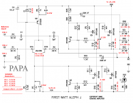
- Pass Labs
- Aleph J Schematic