Short the inputs (pin 1, pin 2, pin 3) There is no whistle.
What's the problem ? How to fix it?
What's the problem ? How to fix it?
Well, you need to distinguish between two very important facts when it comes to building a power amp:
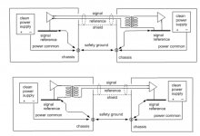
1. DC common returns - your AMP PCB GND return should go to PS PCB zero (0) potential point. Also, the speaker negative should go to PS PCB zero point... just a slightly different path to avoid returning current mixing together.
2. RF noise coupling to the ground - think of what kind of impedance path is required for an HF noise to be coupled to the ground. Your grounding to the common point is anything BUT that.
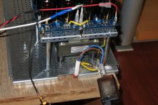
The 220 V AC (Poland, right?) mains IEC connector block shiny metal case is grounded. Scrape the paint from the amplifier back plate, and mount the IEC connector block metal case so that it makes a good connection with the back plate- aim for a wide contact area. Or, use a short multistrand wire and connect the ground lug straight to the either back plate, or the bottom plate.
The PS PCB should be grounded the same way - straight to that red dot - see photo.
The AMP PCB GND should go directly to the PS PCB zero point.
The speaker's negative return should go straight to PS PCB zero point.
That ground lead that comes from the transformer mounting plate (... I think... can't say for sure..), should also be connected to the bottom mounting plate via a short multistrand wire.
Important: the back plate should have very good contact with the rest of the amplifier chassis - scrape the paint and ensure a wide contact area is established.

I have sharpened and brightened your original photo (above)... I hope this is okay with you.
Next, the PS PCB common wiring schedule is shown below:


Aleph J is a fantastic amp.... as such, it does have a very broad frequency range AND a very high input impedance. Hence, it does require a bit of an effort to make sure that all of these benefits are utilised for a positive outcome, and that all the dangers lurking are identified and fixed... The fact that the whistle noise disappears when you short + signal & - signal to ground, should lead you towards ensuring that your source should be of a reasonably low output impedance. If this is the case, the low impedance presented at Alep J XLRs should overcome the whistle noise. Of course, you have to fix the common returns as well.... this is very important.
And finally, I see that you bypassed the C1... great move... I noticed a huge improvement in sound when I did the same. The downside is a 200mV of offset when you turn the amp ON.... however, this settles very quickly to around + and - 10mV, as the MOSFETs heat up & the bias current drops. Also, be careful with DC at the XLR inputs!!! The DC gain is not zero any more!!!
I would not use any intermediate speaker protection boards inside Aleph J.... all the benefits gained by omitting C1 will be annulled by adding additional wiring, relay contact resistance, and the influence of that added PCB on ground uniformity. Get the basics right... and then play with the add-ons later... if you must.
Good luck.
1. DC common returns - your AMP PCB GND return should go to PS PCB zero (0) potential point. Also, the speaker negative should go to PS PCB zero point... just a slightly different path to avoid returning current mixing together.
2. RF noise coupling to the ground - think of what kind of impedance path is required for an HF noise to be coupled to the ground. Your grounding to the common point is anything BUT that.
The 220 V AC (Poland, right?) mains IEC connector block shiny metal case is grounded. Scrape the paint from the amplifier back plate, and mount the IEC connector block metal case so that it makes a good connection with the back plate- aim for a wide contact area. Or, use a short multistrand wire and connect the ground lug straight to the either back plate, or the bottom plate.
The PS PCB should be grounded the same way - straight to that red dot - see photo.
The AMP PCB GND should go directly to the PS PCB zero point.
The speaker's negative return should go straight to PS PCB zero point.
That ground lead that comes from the transformer mounting plate (... I think... can't say for sure..), should also be connected to the bottom mounting plate via a short multistrand wire.
Important: the back plate should have very good contact with the rest of the amplifier chassis - scrape the paint and ensure a wide contact area is established.
I have sharpened and brightened your original photo (above)... I hope this is okay with you.
Next, the PS PCB common wiring schedule is shown below:
Aleph J is a fantastic amp.... as such, it does have a very broad frequency range AND a very high input impedance. Hence, it does require a bit of an effort to make sure that all of these benefits are utilised for a positive outcome, and that all the dangers lurking are identified and fixed... The fact that the whistle noise disappears when you short + signal & - signal to ground, should lead you towards ensuring that your source should be of a reasonably low output impedance. If this is the case, the low impedance presented at Alep J XLRs should overcome the whistle noise. Of course, you have to fix the common returns as well.... this is very important.
And finally, I see that you bypassed the C1... great move... I noticed a huge improvement in sound when I did the same. The downside is a 200mV of offset when you turn the amp ON.... however, this settles very quickly to around + and - 10mV, as the MOSFETs heat up & the bias current drops. Also, be careful with DC at the XLR inputs!!! The DC gain is not zero any more!!!
I would not use any intermediate speaker protection boards inside Aleph J.... all the benefits gained by omitting C1 will be annulled by adding additional wiring, relay contact resistance, and the influence of that added PCB on ground uniformity. Get the basics right... and then play with the add-ons later... if you must.
Good luck.
Last edited:

Thank you for your answer.
During normal operation, the amplifier is completely silent - no hum.
In terms of the "whistle" OK, I will change the creation of a common GDN bus and grounding - you write it shortens the connections to a minimum and it is very logical for me. Thank you.
Regarding the liquidation of the input capacitor: I used the Lundahl LL1581XL transformer - I recommend this solution to omit the input capacitor - the sound is much better and the amplifier is safe.
Attachments
Aleph J already has everything that a great-sounding amp needs. Why would you complicate things?? The addition of an audio transformer can only degrade the sound. Alep J has differential input already. If you have ground issues and need to use an isolation transformer -> the interconnects balanced cable shielding is not required to be connected at both ends!!! Leave it connected at the source end, and floating at Aleph J's end. That's the beauty of a balanced audio signal transmission.
If your aim is to remove C1 - just remove it and pay attention to the source' DC component... at Alep J's input.
If you are worried about the DC component coming from the source and/or you know there's a chance of that occurring => leave C1 in there - this is much better than using any transformer in a direct signal path.... PLUS, you could tune the sound to your exact needs by rolling different C1 capacitors 🙂 something you can not do with that Lundahl transformer.
I was trying to find where exactly you've shown us that Lundalh... but I failed. How did you use it?
By the way, those chokes will be exposed to a fair amount of constant DC current - around 4 amps in stereo (2 AMP PCBs), and around 2 amps in mono (1 AMP PCB). As such, they will generate a fairly strong magnetic field. You'd want to rotate one of them by 90 degrees. Also, move them away from that R-core transformer...
The NOMOBLOCK box is cramped and it is not possible to move the chokes sensibly. Therefore, I will make a screen of 2 mm steel sheet.
Separation of PCB AJ from chokes and transformer. Chokes, current flow directions are connected in opposite directions.
As for the Lunhal, I put it in the Preamp. Output on the Preamp is SE, by connecting the transformer I created XLR. Additionally, there is ground isolation between the source and the AMP. No problem PIN 1.
Attachments

Extreme_Boky
Hello, Redevelopment of GDN done according to your instructions. Positive effect. The whistle stopped working. 2 seconds after the power is turned off, you hear a faint descending hum like the hum of the power grid. The amplifier is quiet during operation, no hum. Now I'm happy 🙂
Once again, thank you very much for your effective help.
Attachments

Yes! Good job, not at all Extreme Boky 🙂👍
Marek PL - The Good times is here, crank it up and Enjoy it 🎷🙂🎸
Marek PL - The Good times is here, crank it up and Enjoy it 🎷🙂🎸
Hi, I would like to ask if the movement of the woofer when the amplifier is switched off is a common problem and if it is possible to eliminate it?
It appears the movement is reduced quite substantially, whit a lower bias current. At least in my setup. Which makes sense... see below.
You'd want the current through output MOSFETs (top pair and the bottom pair) to drop the same way, and as fast as possible.... this is not easy to achieve because two different transistors command how much the MOSFETs (top pair, and the bottom pair) are open when the power is switched off.... the bottom half MOSFETs go closed as soon as the voltage across JFETs diasporas...(the R7 current drops to zero immediately). This is why that negative rail stays charged much longer than the positive.
The top half of MOSFETs are controlled by the gain transistor Q4. It senses the voltage drop across R20-R23 to provide the gain... but this does not work in the amp's favour when the power is removed (turned OFF). When the power is switched OFF, the balance is disturbed in a way that Q4 becomes more open (Vbe becomes high), which forces top MOSFETs to open more and discharge the V+ stored energy quicker.
Differences between discharging times of top and bottom MOSFETs will cause an imbalance at (what should always be) 0 volts at speaker outputs. That point is not 0 volts any more (for a very short period of time) -> and the consequent current flows thru the bass coil.
With the above in mind, it makes sense that the larger the storage capacitance, the higher potential (probability) of more current discharging thru the speaker bass coil (i.e. larger movement), when we switch the amp off.
Also, increasing the value of C3 (allowing the feedback to work for very low frequencies... approach the DC), would probably help here... to prevent that C4 Vbe to become high. Of course, there might be other implications of doing this... that I did not spend time analysing.
Now that I've written the above.... It appears to me that a possible workaround would be to have a relay coil powered up by the positive (V+) rail, and have its relay contacts connected so that the speaker output is connected to the ground (via let's say 2-4 ohm resistor) when we switch the power OFF. The relay contacts will not be inserted in series with the output signal, so no degradation of sound... and we already have a voltage rail that will collapse very quickly, and place the relay contacts in a desired state, therefore preventing the full grunt of that current to run thru speaker windings. The bass cone will still move.... but only a smidge.
The above is my understanding. If I am wrong, I'd love to be corrected.
Last edited:
Thank you Extreme_Boky for the very detailed answer. I actually set the bias to 500mV. This is because I found two very heavy heat sinks (5.5 kg each) and with this bias now with 19°C in the house the heat sink barely reaches 45 °C.
Having read in the forum that the higher the bias the lower the distortion I thought I'd set it high. I could try to use a relay but i don't understand much about electronics, could you kindly show me with a sketch how to connect it?
Sorry for my English.
Having read in the forum that the higher the bias the lower the distortion I thought I'd set it high. I could try to use a relay but i don't understand much about electronics, could you kindly show me with a sketch how to connect it?
Sorry for my English.
Have a listen and see if maybe going down a notch (bias) sounds better to you...? I know that you can dissipate a lot of heat, and I know the amp will have lower distortions as the bias increases... but just try different bias settings in your system... I used to run a 470mV bias on my Aleph J for a year or so... but then one night I decide to play with the bias setting... and figured out that there's a huge sound difference between 470 and 400mV... I settled at 430mV. Just make sure you'll let Aleph warm up properly first... in your case (huge heatsinks)... give it an hour at least.
Regarding the relay connection, see below. My main concern is the contact chattering when the power is switched off... if this happens, use a diode and resistor in series, across the relay coil. The resistor could be 20 ohms.... diode -> any 1N400x
See if it works... I think it should, but maybe I am overlooking something...??
Anyway, there's the 4-ohm/2W resistor there, so you won't be shorting the Aleph's outputs to ground. This resistor will share the bass excursion current with the bass driver. The cone movement will be reduced, but it will NOT be completely gone. If you are brave (and you want to reduce the cone movement even further), reduce the resistor to 2 ohms/ 2W...
Let us know if you tried it, and if it worked for you.
Last edited:
Thanks, first I will try to reduce the bias to 430mV as you did and from the results I will decide whether to use the relay
With the bias adjusted to 430 mV the problem is reduced but not as much as I hoped. I think I'll leave it as it is. The sound is still good.


Hi guys, could someone explain to me what determines the difference in low load capacity between A3 vs Alpeh J?
You will notice that they both share the same power portion of the circuit.
At this point could it be the different front end and LTP that determine this difference?
You will notice that they both share the same power portion of the circuit.
At this point could it be the different front end and LTP that determine this difference?
differences can be ( not saying they are, without looking at schematic, lazy) - source resistor values, set Iq, amount of Aleph CCS modulation (in other words - how much upper portion of circuit is attributing to overall output of amp)
in short - you can vary some things in your own Aleph, to suit your needs and preferences
in short - you can vary some things in your own Aleph, to suit your needs and preferences
With the aim of obtaining a low load capabilities Aleph, which of the 3 (source resistor-Iq-CCS modulation) has more importance?
- Home
- Amplifiers
- Pass Labs
- Aleph J illustrated build guide