Thank you, Jim. Compared to lots of troubleshooting with F6, this one works “ out of box”. I do get a slightly humming noise. grounded at iec and power smoother output side. Will reduce bias (.35v) help (more than quadratically)?
hot box, 8-10c higher than f6. At 18w per channel, no complaint.
wow, fantastic sound - rich and musical.
when I turn off the amp, my speaker woofer baffles sucks in and restores with a short (1/4-1/2 seconds) low (30db - 240hz?) noise. Anyone has similar experienc. i know none-commercial products has such kink - like the famous ACA starting ”fart“.
Attachments
Thank you, Jim. Compared to lots of troubleshooting with F6, this one works “ out of box”. I do get a slightly humming noise. grounded at iec and power smoother output side. Will reduce bias (.35v) help (more than quadratically)?
hot box, 8-10c higher than f6. At 18w per channel, no complaint.
wow, fantastic sound - rich and musical.
when I turn off the amp, my speaker woofer baffles sucks in and restores with a short (1/4-1/2 seconds) low (30db - 240hz?) noise. Anyone has similar experienc. i know none-commercial products has such kink - like the famous ACA starting ”fart“.
Humming amps will only have less hum by reducing bias, if the problem is ripple. If grounding is the issue, reducing bias will help little or nothing.
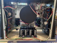
I’d start with the following, looking at your pics:
1: Connect all three green audio gnd/0v wires to the same euroblock on your PSU.
2: Twist your DC and AC wires to and from your rectifiers. They are btw extremely close to the amp boards. Move if possible. Your tranny btw looks awfully large. I hope it is shielded.
3: Please move your AC terminal block to dead center of amp. It is too close to output and input wires. Also, twist all your wires. Start with the most important ones: AC, DC from rectifiers to PSU, and signal.
Then see where you land 🙂
Edited to add/agree with ZM: connect all gnd bridge solder pads on the output side of the PSU. There is room for four links. Only one of yours is connected. Also, you can try cutting the one on the input side, but no guarantee it will help.
Edited to add again: where is your star gnd? Where is the safety earth from IEC inlet connected to chassis? This is important, to not leave your chassis gnd floating in worst case, or worse

Make 1 (one!) common connection to chassis gnd, make sure to file the plating first. Use M4 and not sissy M3 screws, and one of those sharp pointy washers to ensure contact, 6L6 style. Put this connection on chassis floor close to IEC inlet, using at least 2,5sqmm wire. AC gnd cable on the bottom, shield from tranny on top of that, and audio gnd wire with thermistor on top of it all. Tighten like hell.
Regards,
GH4eva
Andy
Last edited:
I guess twisting wires will solve the problem, they cant be left untwisted like that. Twisted wires especially for signal works better than shielded cables in my experience.
Thank you for the advices @strawa @Zen Mod @andynorI guess twisting wires will solve the problem, they cant be left untwisted like that. Twisted wires especially for signal works better than shielded cables in my experience.
Some background info:
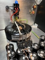
Transformer is a Antek AS5218 with steel shield - that looks very big. Scaled from 300W F6 to 500W for this super charged Aleph J (18W vs 15W from Nelson).
I changed input to balanced (fully, from DAC to Preamp) and the hum is gone.
Single ended hum is background hum - very low volume, both channels. They are higher than 60/120hz (in the States), no meter but my guess is around 200Hz.
Does above tells me this is a surely grounding issue?
I plan to twist and pull away wires green / purple (rectifier heatsink are rather hot, 50C in my room or 28C over ambient).
Relocate the AC block -with dividers to create a little vertical space. You can see the AC wires are actually pulled away (toward transformer case) - should have move the block as well - out of space.
Grounding - I am not able to screw in the star nuts from the diyaudio store kit - m3 - screw in 2 turns and stuck. Will get some M4 star nut (have bolts) to make it clean.
Ground termination is using the big washer.
IEC grounded at top left of picture (you can see a big washer there green wire), 4 screw blocks above left rectifier.
PSU is grounded lower left (from minus side grounding euro block) with a thermistor - green wire.
Grounding wire is 14 AWG - all other wire are 15.5 AWG (even they look thicker).
I am looking to
1. Double grounding from both left and right output euro blocks (one now).
2. Use 12 AWG grounding for IEC.
What do you think, suggestions? Thank you.
Last edited:
If it's me, I will move the AC inlet IEC ground connection to the chassis to the closest possible hole ( as soon as it enters the chassis) on the perforated plate. Then I will take the thermistor with the green wire connected to the PSU board (assuming L and R part of the PSU GND are connected) and connect it to the same point.
I will also move the rectifier board further down, close to the front plate, to get as far as possible to the transformer, and twist and minimize the length of the Live/Neutral coming from the IEC to the the plastic receptacle and move it up and to the left of the transformer.
The goal is to minimize the loop. I think twisting the wires will also help but what you already have looks good to me IMO.
Last edited:
Aleph J original is higher power than you're sayin'
wire thickness for mid IEC pin and for rest of things in same circuit is no issue, as long these wires are stronger than mains fuse
it is good praxis to have all connections to chassis meeting on one chassis point, especially in crowded cases
star nut is not critical - use common nut and split washer
if you have GND bridge on input side of cap bank - cut it, make bridge on output side
as I see it - no hum in balanced is due to better rejection of circuit itself, when fed in balanced mode
The Alephs have a slight turn off thump so what you encountered is expected.
In what way is your Aleph J supercharged?
In what way is your Aleph J supercharged?
I twisted and shortened some where, and relocated the AC block on top of the transformer shield. Hum still there, but case space is a lot cleaner.Aleph J original is higher power than you're sayin'
wire thickness for mid IEC pin and for rest of things in same circuit is no issue, as long these wires are stronger than mains fuse
it is good praxis to have all connections to chassis meeting on one chassis point, especially in crowded cases
star nut is not critical - use common nut and split washer
if you have GND bridge on input side of cap bank - cut it, make bridge on output side
as I see it - no hum in balanced is due to better rejection of circuit itself, when fed in balanced mode
Added and meter checked grounding on IEC, PSU output and input, both boards and XLR connector - all intact solidly.
No asymmetric part in the case anymore. Rectifiers are the closest point to board.
Bias is changing a bit after running it for 24+ hours. Left went down to 387mV while right wend done to 392mV, consequently offset. Re-adjusted both bias with offsets.
The only. remaining option is to cut the grounding bridge at input. @Zen Mod I bridged both input and output by default (works well with F6). Do you see any negative effect if I cut the ground bridge at input. My knowledge is not able to tell - some potential unbalance between the rails?
It is a pain procedure to reattach the front hole-less panel. Front panel needs to be removed in order to cut the bridge at the bottom of the board (mounted to front panel), will let it run for another few days and let the bias further settle before performing this cut. The hum is pretty gentle - sitting 2-3 feet from speakers, audible but not drive me crazy. When I focus I do not hear them anymore. The hum remains constant regardless my input level from preamp.
About power and super charge
In post#3 of this thread, 6L6 pointed the 4ohm resistor 1,000 Hz will resulted 18 watt per channel with offset at 400mV.
From firstwatt.com Aleph J page, it shows 4ohm => 15 Watt.
My speakers ranges from 3.2 (300-400Hz) to 12.3Ohm through spectrum of 50-15,000Hz. It averages 5.6 and focus around 4ohm at vocal range. I always use 4 ohm as output metrics - not 8 ohm. My apologies for the confusion.
I'm not having exact experience with that pcb, just pointing on fact I did read here and there
Better to wait that someone actually having pcbs in amp say about own experience
if you use M4 headles screws ( don't remember proper name in English) for front plate, along with split washers and nuts, dealing with FP should be easier
just for fun - use fatter wire with crocs , temporary connect main GND point on one channel pcb with same on other channel pcb
power On, inform what's happening with hum level
I see this in post #3:
"Now to increase the bias to the recommended amount, 400mV (I had it just on the edge and the meter read .39 when I took the photo….) 400mV bias = .85A = 18W/device"
The 18W here refers to the each mosfet's dissipation. 6L6 measured distortion for ~1W into 4 ohms at different levels of bias current.
I want to thank Octopus Technicus for sharing his superb CAD drawing, now on the wall of my kitchen 🙂


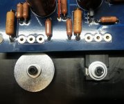
Yes. Its good fastening and heat transfer. But it looks bad and sloppy.Is the left one too big?
✋😇
I miss the information regarding country of origin for all of the fearless builders on teh spinning globe. The blue dot.
It was simply oldscool cool 🙂
It was simply oldscool cool 🙂
I miss the information regarding country of origin for all of the fearless builders on teh spinning globe. The blue dot.
It was simply oldscool cool 🙂
I miss that too.
@Zen Mod I tried to short the ground with a 10 AWG wire, did not change anything.I'm not having exact experience with that pcb, just pointing on fact I did read here and there
Better to wait that someone actually having pcbs in amp say about own experience
if you use M4 headles screws ( don't remember proper name in English) for front plate, along with split washers and nuts, dealing with FP should be easier
just for fun - use fatter wire with crocs , temporary connect main GND point on one channel pcb with same on other channel pcb
power On, inform what's happening with hum level
I also made a cut grounding bridge on the smoother part of PSU input, did not work out - it should - read a lot of things and that's likely the problem of neg / pos rejection - espeically same level of humming on both channels regardless of preamp level.
Just in case, also tried to reduce bias to 350mV - that's not the problem either (even 250mV) - expected.
Do you think its the problem of RCA female to XLR male Neutrik converter ($7 a piece, checked wiring and insulation, correct).
Guess I will live with the XLR happily forever? Thanks again.
Thanks a lot for the trick of using a longer bolt (do not know the bolt name either) to thread in and use a nut on the bolt to fasten. That works REALLY well.
Chassis is a lot cleaner - all the helps, temp remains similar. A fan fact is the outer heatsinks are 2C higher than the inner heatsink. Guess that's a result of heat evens out after penetrating through the 8mm heat sink panel. Hottest point is still the pin of the transistor. on the bias pot end - 62C. Inner heat sink cross top region is 48-49C (left a little cooler). Out heatsink (not the fins) is about 51C, fin tip is 43-48C, hard to measure.
Last edited:
- Home
- Amplifiers
- Pass Labs
- Aleph J illustrated build guide