Hi there,
I´d be happy if you could help:
Must R16 to R23 (0.47R / 3W) be matched to a closer tolerance than 5%?
If yes, would be Mills wire wound 1% be an option?
My multimeter doesn´t measure this bandwidth.
Many thanks for the help.
Rents
I´d be happy if you could help:
Must R16 to R23 (0.47R / 3W) be matched to a closer tolerance than 5%?
If yes, would be Mills wire wound 1% be an option?
My multimeter doesn´t measure this bandwidth.
Many thanks for the help.
Rents
Hi there,
I´d be happy if you could help:
Must R16 to R23 (0.47R / 3W) be matched to a closer tolerance than 5%?
If yes, would be Mills wire wound 1% be an option?
My multimeter doesn´t measure this bandwidth.
Many thanks for the help.
Rents
In my experience using Panasonic metal oxide resistors, is that just randomly selecting resistors leads to better than 2% matching anyway, so I wouldn’t worry.
The tolerances are better than what the specification states.
@srt1castle,
Before you start, with amp power off, can you check the resistance of the R7 offset pot?
If it measures significantly over 1K, can you turn it back down to about 1K?
Before you start, with amp power off, can you check the resistance of the R7 offset pot?
If it measures significantly over 1K, can you turn it back down to about 1K?
Thanks for the information and I will try that. The output transistors are approaching 62C so have not tried to bias any higher. Back to your advice. So should I put jumpers in place of the resistors that are called out? Then maybe the offset trimmer will work better? I am terrible at reading resistor colors. I may un- -solder one end and read it first. Again thanks for your time and will report back later.
@srt1castle,
Before you start, with amp power off, can you check the resistance of the R7 offset pot?
If it measures significantly over 1K, can you turn it back down to about 1K?
I took reading and had about 1.9k ohms. Adjusted down to 1k ohm and turned on amp and still read 18 VDC on speaker output. Tried again and got to 16VDC. The trimmer appears to work up to a point. Dropped trimmer to 500ohms and still no real change. Trimmer will read any ohms adjustment that it gets set at. Thanks for your input
There's no need to replace those resistors with jumpers now.
If you can post a bright and in-focus photo of the R6/R30 area we should be able
to verify their values. R6 looks like 562 from one of your earlier photos.
Once that's verified you can start getting the front end in the proper operating range.
Also, please turn down the bias (say to below 200mV over the 0.47 ohm resistors). You can
start bringing that back up once the front end current is ok.
Last edited:
Small world - off topic
I rarely see anyone from Hudsonville - the salad bowl city, with a salad bowl parade and a salad bowl queen.
Hey kstagger. Assuming you're in Grand Rapids MICHIGAN, I live in Hudsonville and can give you a hand.
I rarely see anyone from Hudsonville - the salad bowl city, with a salad bowl parade and a salad bowl queen.
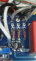
Here are two pictures. Taking close up noticed Q2 emitter not appeared soldered from top side like collector and base. Re soldered and turned back on and no difference.
Maybe the color bands.
R6 color bands GRN, BRN, BLU, RED,BLK, Brown
R30 color bands BRN, BRN, GRN, Violet, Yellow
Maybe the color bands.
R6 color bands GRN, BRN, BLU, RED,BLK, Brown
R30 color bands BRN, BRN, GRN, Violet, Yellow
Attachments

Pretty sure R6 is 562R. As others have suggested, please check all soldering
and reflow any that may look suspicious.
Lower the bias and then power off. Set R7 trimmer to about 1K.
Then power up and adjust LTP trimmer until you get about 4.7V across the R6
(562R resistor). (so you have about 8.4mA going to the front end jfets)
Now check bias and dc offset and try adjusting offset.
Attach top of resistors to pads closest to wires and report back.
Soldered extensions on both channel boards on the three resistors. Read voltage and got .486 VDC and thought man that is great. Well output transistors R20,21,22,23 read 0VDC. Cold Cold and not able to adjust to get any voltage on those.
Other board still heats up with about .419VDC on output transistors but speaker output leads still read this time about 19VCD. Trimmer pot could not make a change to the high voltage. Removed voltage and thought will try to measure resistance across the three extended leads on resistors across resistors. Read steady .2 ohms on both left and right channel boards. Just trying see if can compare to maybe try to find out why channel is dead. Can read +24VDC and -24VCD into the now dead board. I am brain dead for today and will get back to this tomorrow.
I DO APPRECIATE all the suggestions. So close...........
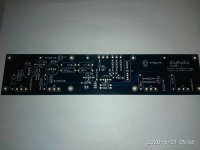
I regret now not taking picture of unpopulated boards so could read the board number item locations. If anyone could post a picture that we ALL could use please do so. THANKS
Will it be a Canadian beer or Colorado beer next?. How about both.
Attachments

Did you lift the leads that were at the top of the resistors or just solder extensions?
Did not lift leads to solder extensions. I will take board off of heatsink tomorrow and do it right. Got new spare output thermal pads today as backup. Not sure if can re use old thermal pads. Hope to just maybe bend up board and work from bottom to resolder what I can. thanks again.
I remember doing similar circular problem solving at work (retired now). Obviously I did bad solder work on the one side that is dead for now.

Yes you can re-use pads, make sure there’s no metal crumbs.
Get resistors from the top to the bottom pads. Your resistors (and inputs) were floating before, now the the inputs are shorted to ground.
Get resistors from the top to the bottom pads. Your resistors (and inputs) were floating before, now the the inputs are shorted to ground.
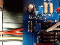
Here is another pic...
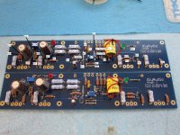
Thanks so much for that. Crisp and clear. In the meantime from this afternoon went and used various pictures of the builds to annotate a picture from the forum. Thanks to whomever submitted the original picture as I used it at various times. Now that it is populated along with annotations may it be of some use to someone else besides me.
Attachments
Hold the thermal pads up to a bright light to check for punctures or pinholes before re-using.
Thanks so much for that. Crisp and clear. In the meantime from this afternoon went and used various pictures of the builds to annotate a picture from the forum. Thanks to whomever submitted the original picture as I used it at various times. Now that it is populated along with annotations may it be of some use to someone else besides me.
Great looking boards...
- Home
- Amplifiers
- Pass Labs
- Aleph J illustrated build guide