I am in the process of gathering parts for an AJ build and am very excited about the learning process associated with it. I have purchased some boards, a P.S. board and C grade lsj74's from the diy store. After reading the posts and looking at the schematic I see that the "B" grade jfets with an IDSS of about 8 mA are the preferred ones. From what I can figure they biased at their IDSS value give R7 the correct voltage for the correct Vgs of the op mosfets. In addition the 9.1V zener and voltage across r8 properly bias Q2. I hope I'm not wrong with this as I suspect the lsj74's I have ordered will have a higher IDSS ( 10 - 20 Ma). So if in fact I have say 2, 15mA fets I think changing the the zener D1 to 14 volts give me the correct voltage across R7 and also allow me to adjust the offset properly. From what I can tell from the data sheets for the 2sj74 the transconductance difference of the different grades is minimal. Am I on the right track or am I completely in left field on this?
Thank you for the quick reply. So you are saying that there is enough adjustment with the r8 and r7 pots to take care of this? Either way you have saved me some time and trouble and I thank you for that. Can't wait to hear this baby, from all I've read it is awesome!
R7 and R8 - yes
just be sure to preset them to regular values , shown in Papa's schm
don't use both resistors and pots in those positions - use ether pots or resistors
just be sure to preset them to regular values , shown in Papa's schm
don't use both resistors and pots in those positions - use ether pots or resistors
How can match the transistor mosfet? Is it the same system as the jfet?
I've seen some forum member put to C1 a capacitor Auricap or Mundorf. Is this option valid only for balanced input?
I've seen some forum member put to C1 a capacitor Auricap or Mundorf. Is this option valid only for balanced input?
Concerning the PSU caps, since Pass amps run fairly hot, I'm considering to choose 105° capacitors (Nichicon GU series). Is good or is it overkill?
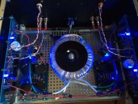
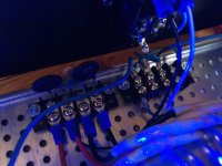
OK ... I need help form the gurus ... I have tried everything and can't get rid of the hum!
AC GND In attaches to Chassis and then though CL60 to Aleph L&R channel GNDs from a single star point. All wiring is separated by at least an inch. Touching the wires does nothing except when I touch the input wires I get a loud hum but not the same hum as the constant one ... another one on top of the one I can't eliminate! I have the AC mains filter across the input then CL-60 in series with each leg of the transformer. Power supplied through an APC conditioner that has an isolation transformer.
I've read about rotating the toroid to see if that makes it go away, but like an idiot I cut the wires exactly to length to keep the wiring tidy.
Any other ideas?
FWIW ... I am running 102dB Cornwalls ...
Attachments
Just a thought ... what if I pick up a piece of aluminum screen at the hardware store and wrap it around the toroid and then tuck the bottom beneath the tori and the chassis and tighten it back down?
Essentially a Faraday cage around the toroid?
Essentially a Faraday cage around the toroid?
Aluminum is non-ferrous, won't work as a Faraday cage.
You have an enormous ground loop... mainly because the PSU board is spilt and you have no central point on it, but also as you have all the grounds bussed on the PCB and then have the greens running to the CL-60 and Chassis earth... and those are in the magnetic field of the transformer...
Check your PM
Jim, good news, the BA-3 board and soft start board (and F-4 boards too) have been shipped from the store. Next amp to finish is the Aleph J. I've got so many kits laying around, I'm not sure which Mosfets (Outputs) were included in the Aleph J Kit I got from You. Its 8 pieces for two channels, (four per side) right? I think I have it narrowed down to bags of IRF, The only other set of 8 I can find are Faichilds, and I think those were for the Turbo F-5.
Thanks in advance for the memory jog,
Russellc
Thanks in advance for the memory jog,
Russellc
The Aleph transistors in one of the kits I sold will be (8) pc of IRF240, and they will have fairly large numbers written on the back of them, and those numbers are arbitrary, not actual Vgs values.
Should also be in a mylar ziplock bag about 3"x5". Tha bag may or may not have anything written on it depending on which batch of kits is was...
Should also be in a mylar ziplock bag about 3"x5". Tha bag may or may not have anything written on it depending on which batch of kits is was...
The Aleph transistors in one of the kits I sold will be (8) pc of IRF240, and they will have fairly large numbers written on the back of them, and those numbers are arbitrary, not actual Vgs values.
Should also be in a mylar ziplock bag about 3"x5". Tha bag may or may not have anything written on it depending on which batch of kits is was...
Thanks...I have a confusing amount of kits and parts! I'm cleaning several of them up! Thanks for the Info!
Russellc
I'm in the process of building a new enclosure for my Aleph J. The goal is to bias the AJ a lot higher because in the 3U 300mm store cabinet I couldn't bias higher than 0.85 Ampere/ output device.
In the new cabinet I can bias with the trimpot till 1.2 Ampere/ device and then I reach the end of the 100K trimpot. This is R27 in the FW Alepgh J schematic and is original 68K2.
How can I bias the Aleph J higher? Even higher resistance than the 100K pot, by placing a 47K in series? Or should I better change other resistor values in the AJ current source?
Heatsinks are only 46 degrees with 1.2 Amp / device, so I can bias 10 degrees higher 😀
Will post pictures later....
- Home
- Amplifiers
- Pass Labs
- Aleph J illustrated build guide