@MK57,
I've been in the same place. I find that the best way to show photos is to size them to about 800 x 600 and save them as an attachment. Below the "Reply to Thread" box there is an "Additional Options" box. Inside that is a "manage attachments" button that will let you attach bigger photos. Give it a try.
I've been in the same place. I find that the best way to show photos is to size them to about 800 x 600 and save them as an attachment. Below the "Reply to Thread" box there is an "Additional Options" box. Inside that is a "manage attachments" button that will let you attach bigger photos. Give it a try.
Just stuffed my first board and noticed that I have orientated the trimpots at R7 and R8 backwards. I assume the arrow on the PCB is to illustrate the direction of pins 1,2,3?
However I am surmising that this shouldn't matter - I can still adjust trimmer resistance - just that the screw direction will change. Am I correct? Or do I need to unsolder and replace?
Thanks in advance for your help, and for this great thread!
However I am surmising that this shouldn't matter - I can still adjust trimmer resistance - just that the screw direction will change. Am I correct? Or do I need to unsolder and replace?
Thanks in advance for your help, and for this great thread!
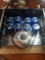
OK, my turn for a question. Below is a dry fit for my Aleph-J. I'd like to use these big cans since I have them - 68,000 µF/50V reformed since sitting on my shelf a few years away from this hobby. Layout is for dual CRC PSU sharing a common transformer.
My concern is the proximity of the outer caps to the boards, especially the input section on the left. If I go this way the outer caps will be the final caps and connect to the board. AC will run below the tray. I bought a bunch of grommets to do that safely.
So the question is should I go this route or a single shared CRC PSU or separate C only PSUs? Thoughts and ideas welcome.
Attachments
CRC.
Go to the local hobby store and get some copper sheet and make a solid copper GND in-between the capacitor's screws, run all the grounds there and it will be really quiet. There is plenty of room between the various screw terminals to mount the filter resistors.
Go to the local hobby store and get some copper sheet and make a solid copper GND in-between the capacitor's screws, run all the grounds there and it will be really quiet. There is plenty of room between the various screw terminals to mount the filter resistors.
Without drilling new holes in the base, the caps are a bit further apart than my dry fit. the only way to mount the transformer is vertically. I remember seeing a bracket but can't remember where. Did anyone bookmark that? The only ones I've been able to find are pretty flimsy looking and create a shorted turn if the insulating washer fails.
I might be able to fit a pair of Antek 4220s stacked.
Thermistors are in the plan.
I might be able to fit a pair of Antek 4220s stacked.
Thermistors are in the plan.
Found the L-bracket source - Apex Jr.Home Page Not listed on the site, but call Steve to check availability.
Hope that helps someone else.
Hope that helps someone else.
Voltage Offset Variance Drift
Hoping one of you knowledgeable folks on the forum may have checked the DC offset as described below.
Initial set:
Did you determine that after initial warm up and set of the output voltage DC offset to 0V, there was any drift? If so, how much, and over what time period?
Verification at some other point:
After doing the initial procedure, the amplifier has been shut down and is cooled off. It's then powered up; what did you measure for offset under this scenario, and how long did it take to go back to 0V (or as close as it got) ?
Thanks for taking the time to respond.
Last edited:
inputs shorted for test ;
generally for Aleph series :
cold state - anything up to 400mV , 0mV at temp equilibrium
no probs even with Lowther-like fragile spks
generally for Aleph series :
cold state - anything up to 400mV , 0mV at temp equilibrium
no probs even with Lowther-like fragile spks
inputs shorted for test ;
generally for Aleph series :
cold state - anything up to 400mV , 0mV at temp equilibrium
no probs even with Lowther-like fragile spks
Thanks ZM, good to know most speakers can endure up to 400mV DC offset. That will be useful information for what I am working on.
However, as per the question, I'm (also) seeking specific information about the characteristics of that DC offset behavior with respect to temperature/time, at initial set and on subsequent power-up states. 🙂
The rule of thumb for these amps is everything might be in flux until totally warmed up, I.E., 1/2 hour powered on.
....
However, as per the question, I'm (also) seeking specific information about the characteristics of that DC offset behavior with respect to temperature/time, at initial set and on subsequent power-up states. 🙂
well , I told you specifically ; pardonne moi - I'm not remembering polarity of said offset , and now I'm too lazy to think about tempco of parts involved
😉
- Home
- Amplifiers
- Pass Labs
- Aleph J illustrated build guide