Don't worry about the bypasses. Especially if you are using silmics. Use them or leave them be, whatever makes you feel better about the build.

Darn it Jim ! I am just about getting ready to build my F5 based on your guide, now you shove this in my face?
Another great guide that will inspire many to build 🙂
Make a few extra connections to the PSU output of your F5, and with little effort you can swap the Aleph J PCB in place of the F5 and vice-versa. The big expensive case and PSU need only be bought/built once. 😀 😀 😀
Yes, it's that easy.
Have you ordered the Aleph J PCB yet? 😛😛😛
Sorry I typed, F5 when it should have been F4.
LOL, heck no......still trying to get all the parts through front door for F4 without being caught by wife 🙂
LOL, heck no......still trying to get all the parts through front door for F4 without being caught by wife 🙂
Jim
Just a few notes on the Store boards.
I find them quite a challenge to solder compare to some other boards. The solder don't really want to take to the pads even though I cleaned them with rubbing alcohol.
Also I see with the newest layout that the resistors around C2 is very tight if you are going to use the RN60D resistors. My suggestion to fellow solder slingers is to rather avoid that annoyance and use smaller resistors in these positions if they are super fussy about a neat layout.
I will post a pic later tonight. At the moment I have a few steaks on the barbie, so I can't do it right now.
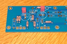
Attached is a pic where one can see the tight area around C2. With the new layout allowing for a bigger cap things will be very tight when using that bigger cap, and with RN60 resistors might even be impossible to mount a bigger sized cap for C2. So beware.
Attachments
Last edited:
Jim-what are those bridge rectifiers? I can't seem to find them at digikey in fast recovery type.
Hi guys, I am ordering parts for this amp and antek does not have 300 or 400 18v transformer in stock. Would it hurt to go to 16v.or 20 v? I assume this would impact the bias also. Any advice appreciated.
thanks, John
thanks, John
20
in that case , no 25Vdc rated caps , but more
no change of bias needed , that's eeeny weeeny difference
in that case , no 25Vdc rated caps , but more
no change of bias needed , that's eeeny weeeny difference
I ordered the 500VA with 18v secondaries. I gave thought to the 600VA with 4x 18v, and doing 2 separate rectifier/capacitor sets, but figured I could do better stuff on a single set. The interior of the case will have more room.
I plan extra effort on the push button and soft start circuits, along with trying to really separate PSU from the signal sides.
I plan extra effort on the push button and soft start circuits, along with trying to really separate PSU from the signal sides.
Jim,
Thanks much for getting this up. I'll be looking forward to getting started fairly soon.
-- Jim
Thanks much for getting this up. I'll be looking forward to getting started fairly soon.
-- Jim
Jim-what are those bridge rectifiers? I can't seem to find them at digikey in fast recovery type.
They are not fast-recovery. It's best to avoid fast diodes in a Class-A PSU.
Papa talks about it here - https://www.passdiy.com/project/articles/power-supplies
This is the part I'm using - GBPC3502-E4/51 Vishay Semiconductors | Mouser
With the new layout allowing for a bigger cap things will be very tight when using that bigger cap, and with RN60 resistors might even be impossible to mount a bigger sized cap for C2.
There are a number of ways to avoid having a problem, the first is obviously to use smaller components.
But in lieu of that, the resistor can always be mounted higher and bent out of the way, or
You could mount it soldier-style and have only the thin lead on that side, or
You could mount that resistor on the bottom of the PCB.
All those solutions work well.
They are not fast-recovery. It's best to avoid fast diodes in a Class-A PSU.
Papa talks about it here - https://www.passdiy.com/project/articles/power-supplies
I don't quite see the reasoning there. Are they noisier? Also, this is a piece of conflicting information.
Jim, in your bias setup last 2 distortions are 0.07% and then 0.45% - did it increase with a higher bias or it is a typo?
Oops! 🙂 Forgot a zero... The 500mV (very hot) bias should be 0.045%
That's why I have the photo of the meter - you can see that it's lower.
That's why I have the photo of the meter - you can see that it's lower.
- Home
- Amplifiers
- Pass Labs
- Aleph J illustrated build guide