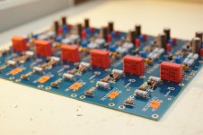
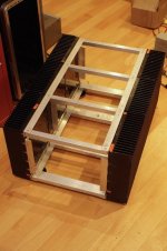
I just finished (6) Aleph-J boards and a custom enclosure for the active crossover (6 ch) system.
Now I have a few questions about the grounding. I have been learning it for a few night, but I can't still find what is the least problematic method.
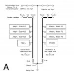
Please find attached files and let me know what do you think, I made A and B, for example. A few pictures of my project are also attached. The amp has 2 transformers and 2 PSU in one big chassis.
Now I have a few questions about the grounding. I have been learning it for a few night, but I can't still find what is the least problematic method.
Please find attached files and let me know what do you think, I made A and B, for example. A few pictures of my project are also attached. The amp has 2 transformers and 2 PSU in one big chassis.
Attachments

Last edited:
Hi Zen Mod, thank you for the advice, quick 2 questions,
1. Is there any other "potentially" better way than B?
2. Regarding A, Ground Buss or Star Grounding idea itself is less preferable? or the connecting Speakers directly to the Buss is bad?
1. Is there any other "potentially" better way than B?
2. Regarding A, Ground Buss or Star Grounding idea itself is less preferable? or the connecting Speakers directly to the Buss is bad?
That's a serious setup!! What are the dimensions of the heatsinks? Are you going to build any fan assistance?
They are industrial surplus heat sinks from Ebay with serrated 3" depth fins. I believe no fan will be required, but fingers crossed... The enclosure is huge, 24x19x12 inch (60x50x30cm).
An illustrated guide to building the Aleph J
Power Supply
The power supply for the Aleph J is going to follow the basic pattern of the Pass/Firstwatt DIY amplifiers. Please look at the following schematic --
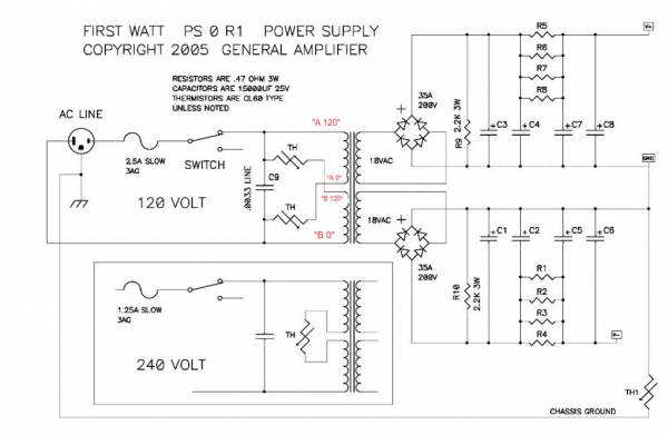
The basic topology is this. 18+18V transformer, of at least 300VA, CRC filter with 8 15,000uF 25V capacitors and 8 (4 per rail) 0.47ohm 3W resistors.
May you use a transformer with more VA? Yes, of course.
May you use larger Capacitors? (more uF) Yes.
May you use capacitors with a different voltage rating? Yes, as long as you have 25V or more. (25V, 50V, etc…)
Remember that the factory Firstwatt amps use 300VA transformers and (8) 15,000uF 25V caps. If that's good enough for Papa… It should be good enough for you. But almost everybody makes it bigger. No problem at all. It's easy, so you might as well... 🙂
In this build I am using the old (smaller) DIYaudio PSU board. This particular one has no blue soldermask on the top of the PCB. It is otherwise identical. The section for the discrete diode bridges has been snapped off.
For some reason I can get the LED color correct on this PCB… Red for V+, Green for V-
You are free to comment or question. 😀
Is there a guide that explains how to customize the PSU for the Aleph J? On the BOM it mentions that the CRC filtering is optional. Should it be implemented? How should I implement the snubber circuit? I'm a few years behind getting started on my Aleph J build. 😉
6L6, what values for R1-R10, R_Optional1-R_Optional-6, and R20-R21?
They show .47 - 1R, 4.7K-22K, and 4.7K-10K.
Thanks!
They show .47 - 1R, 4.7K-22K, and 4.7K-10K.
Thanks!

In your PSU build guide photos, I see two 2.2K bleeder resistors. Do I need those? Are those R9 and R10?
Pass DIY Addict
Joined 2000
Paid Member
Bleeder resistors are not required, but they are a good idea while you are actively working on your amp. As you power up and power down, disconnect things, reconnect things, and keep working, the bleeder resistors will discharge the PSU caps fairly quickly and prevent potential nasty surprises as you work.
A few months ago, I lost a regulator and a few downstream components while working on a circuit because my PSU caps still had significant charge in them the next day.
A few months ago, I lost a regulator and a few downstream components while working on a circuit because my PSU caps still had significant charge in them the next day.
Bleeder resistors are not required, but they are a good idea while you are actively working on your amp. As you power up and power down, disconnect things, reconnect things, and keep working, the bleeder resistors will discharge the PSU caps fairly quickly and prevent potential nasty surprises as you work.
A few months ago, I lost a regulator and a few downstream components while working on a circuit because my PSU caps still had significant charge in them the next day.
Yup. When its all built, the amp drains it almost instantly. While you are working on it is the trick! I fired up the power supply all the way up to the recifiers just to measure voltage and make sure I wired the barrier strip with the 2 CL-60s and capacitor on the primaries correctly, and seeing it was correct, went to bed. The next day I was cutting to length the leeds coming off the power supply, got in a hurry not thinking and cut 2 at the same time. The resultant flash and spark caused no damage to me, but burned a nasty notch in both cutting edges of a $30.00 pair of Xcelite Cutters.😡 I just failed to drain off the juice and it really retained a wallop!
Russellc
I also put LEDs in series with the bleeders so I can see the PS is powered up.
As others have mentioned, without a load, caps can retain voltages for quite
a while. I was reforming a fairly large cap and did not drain it after charging.
The voltage had only gone down by a couple of volts over a week later.
Dennis
As others have mentioned, without a load, caps can retain voltages for quite
a while. I was reforming a fairly large cap and did not drain it after charging.
The voltage had only gone down by a couple of volts over a week later.
Dennis
When selecting the diodes for the PSU, the notes in the BOM say the reverse voltage rating depends on the transformers secondary voltage. For the Aleph J because my secondary voltage will be 18v, will a diode with a 50v reverse voltage rating be sufficient?
An excellent choice, i used those in both my BA-3 and F-6 amplifiers, and just ordered them for the M-2 I am building now. My first amp, the F-5 I used Peter Daniels rectifier boards and individual (8 per channel) MUR rectifiers. They worked beautifully, but took up a heck of a lot more floor space, required numerous solder joints. These that 6L6 is showing you here also work beautifully, take up very little floor space and are WAY less expensive than the route I took with the F-5.
Russellc
Another Aleph J clone ready...
More pictures here: Aleph J
Thank you for an excellent build guide! 🙂
An externally hosted image should be here but it was not working when we last tested it.
More pictures here: Aleph J
Thank you for an excellent build guide! 🙂
- Home
- Amplifiers
- Pass Labs
- Aleph J illustrated build guide