I just hooked up my speakers and heard a very loud pop. Then smoke came out of the left speaker cabinet!

Sending the bill from my cardiologist your way.

JUST PLAYING guys.
Thank yall so much🙂
Congratulations! Way to stick with it. Enjoy the tunes.
Just read this KP. Sooooooooo happy you got it sorted! What a journey!
Postmortem.
So do you think you must have cooked those mosfets? Do you use a heatsink clamp on each leg when soldering them? I use that on the small transistors but this time I didn't bother with the mosfets cause I think they can stand a standard solder up.
Otherwise is there anything that you learned in this build? I mean anything that stands out? Just for others who follow you know.
Maybe a discussion on the type of soldering iron you used?
My first build I used a great old Scope with a big tip and somehow I didn't cook anything. I now have one with a fine tip that I use with very fine solder and I like it much better.
Cheers and congrats anyhow!
Wot,Just read this KP. Sooooooooo happy you got it sorted! What a journey!
Postmortem.
So do you think you must have cooked those mosfets? Do you use a heatsink clamp on each leg when soldering them? I use that on the small transistors but this time I didn't bother with the mosfets cause I think they can stand a standard solder up.
Otherwise is there anything that you learned in this build? I mean anything that stands out? Just for others who follow you know.
Maybe a discussion on the type of soldering iron you used?
My first build I used a great old Scope with a big tip and somehow I didn't cook anything. I now have one with a fine tip that I use with very fine solder and I like it much better.
Cheers and congrats anyhow!
Thank you for asking about this build. Looking back there were two critical errors on my behalf:
1. When I ordered parts from the DIY store I ordered the " Matched quad " of jfets with included LSj74 / LSK170, because they were sold out of matched quad LSJ74.
I made the assumption that LSK 170 was another option for Aleph J. How wrong I was on that idea.
I replaced Jfets with proper parts and only 1 channel worked at this point..
2. It was brought to my attention that I had too much flow up the legs on the jfets and I may have possible cooked them. So this leads me to replacing the jfets once again.
However this time I made sure to quickly and lightly flow the solder joints.. Now things were getting voltages in places that were not working before on the boards.
I still had an issue of a pair of mossfets on the right board that were an issue.
I ended up with much troubleshooting advice and it lead me to Replace Q5 and Q6. R17 kept getting smoked after just a few minutes of the amp powered on.
I happened to have a pair on hand of jfets from previous build. Dual mono AMP Camp Amps build with premium parts
So I replaced Q5 and Q6 and I was back in business.
I have a little soldering experience from building successfuly several Quadcopters and the two mentioned amp camp amps.
So I can and do normally solder lightly, we will call it.
I watched a video linked inside Aleph j build guide and watched a gent build a power supply. He was really heating and flowing that solder. I thought hey I probably need a super joint like this guy is making. Haha.
So I am assuming I cooked mossfets / jfets that were acting up but I can't be certain.
Those were the only errors I made soldering too hot to these delicate parts.
The build guide was amazing as was the help here on this community of DIY experts.
Thank you all for helping me along this journey.
Cooling Aleph J
Dear supporters,
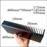
I'm in process building Aleph J. I have relatively small heat sinks measured 400mmx115mmx with fins 50mm.
Mounting fans directly on heatsinks outside of chassis is not what I want.
Is there any benefit mounting fan (or two fans) on the back of the chassis blowing air in side???
Thank you,
Regards,
Dear supporters,
I'm in process building Aleph J. I have relatively small heat sinks measured 400mmx115mmx with fins 50mm.
Mounting fans directly on heatsinks outside of chassis is not what I want.
Is there any benefit mounting fan (or two fans) on the back of the chassis blowing air in side???
Thank you,
Regards,
That heatsink is indeed quite small.
For the best results, you would have to place the fans underneath the heatsinks, blowing upwards. Maybe 4 or 6 fans in total, 2 - 3 per side...?
9Blades 12V 0.08A 50mm Cooling Computer Fan 5010 50x50x10mm DC 3D Printer 2-Pin | eBay
For the best results, you would have to place the fans underneath the heatsinks, blowing upwards. Maybe 4 or 6 fans in total, 2 - 3 per side...?
9Blades 12V 0.08A 50mm Cooling Computer Fan 5010 50x50x10mm DC 3D Printer 2-Pin | eBay
Attachments
That's exact heat sinks that I'm going to use...
Probably it would be the best solution to put small fans underneath... I'll figure something 🙂
Thank You very much on Your help
Regards
Probably it would be the best solution to put small fans underneath... I'll figure something 🙂
Thank You very much on Your help
Regards
You can put two heat sinks together and make some kind of tunnel. Then you can put 100x100mm pwm fans on the ends of the tunnel. It would be more silent then smaller fans underneath.That's exact heat sinks that I'm going to use...
Probably it would be the best solution to put small fans underneath... I'll figure something 🙂
Thank You very much on Your help
Regards
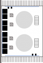
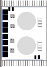
I’m hoping to guild an Aleph J set up as dual mono and I’m trying to see if it can fit in the DIYAudio Store’s 4U deluxe chassis. I was thinking about putting the filter capacitor boards on the front of the chassis and leaving the toroids flat against the bottom. I started to put together a wiring schematic for myself, but I noticed that C2 & C3 on the amp board might not squeeze by the filter capacitors (see the pictures below – the location of the caps on the amp board are approximate; the rest should be pretty close). Using shorter caps on the amp board could help, but is there a concern in having the amp's caps so close to the filter caps? Has anyone else attempted this, or am I just trying to squeeze too much into too shallow of a chassis?
Attachments
That's the exact heat sinks that I'm going to use...
Probably it would be the best solution to put small fans underneath... I'll figure something 🙂
Thank You very much for Your help
Regards
Anytime.
Consider what dabochkarev is saying as well.
If you stick with something similar to my suggestion, run the fans at 10V DC, which will provide sufficient airflow, and will make them less noisy.
You can choose very quiet fans as well, like Fractal Design, 12V DC. Running these at 10V DC will make them completely quiet!
Last edited:
I’m hoping to guild an Aleph J set up as dual mono and I’m trying to see if it can fit in the DIYAudio Store’s 4U deluxe chassis. I was thinking about putting the filter capacitor boards on the front of the chassis and leaving the toroids flat against the bottom. I started to put together a wiring schematic for myself, but I noticed that C2 & C3 on the amp board might not squeeze by the filter capacitors (see the pictures below – the location of the caps on the amp board are approximate; the rest should be pretty close). Using shorter caps on the amp board could help, but is there a concern in having the amp's caps so close to the filter caps? Has anyone else attempted this, or am I just trying to squeeze too much into too shallow of a chassis?
The good thing about C2 and C3 is that you could try to mount them parallel to the AMP PCB, by extending their leads a bit to allow for a 90deg bend, if you absolutely must do so... The PS caps and the C2&C3 can reside close to each other, as long as the exposed aluminium surfaces at the top are not touching.
I’m hoping to guild an Aleph J set up as dual mono and I’m trying to see if it can fit in the DIYAudio Store’s 4U deluxe chassis. I was thinking about putting the filter capacitor boards on the front of the chassis and leaving the toroids flat against the bottom. I started to put together a wiring schematic for myself, but I noticed that C2 & C3 on the amp board might not squeeze by the filter capacitors (see the pictures below – the location of the caps on the amp board are approximate; the rest should be pretty close). Using shorter caps on the amp board could help, but is there a concern in having the amp's caps so close to the filter caps? Has anyone else attempted this, or am I just trying to squeeze too much into too shallow of a chassis?
As ZM wrote me, better to go for Dissipante 4U/400mm for dual mono and make holes by your own
A tip from you,
I want to put an input fuse on AC 230V, what amperage should I use?
2A 250VAC or higher?
I want to put an input fuse on AC 230V, what amperage should I use?
2A 250VAC or higher?
Yes, 2A on 240V is what Nelson Pass recommends in his Aleph J documentation.
https://firstwatt.com/pdf/prod_aj_man.pdf
https://firstwatt.com/pdf/prod_aj_man.pdf

(@peppenino ) I instead the cabinet and two 1uF mundorf capacitors. I hope I haven't made any big mistakes ..

Old brown Pannies for me... Pity that the lead spacing not allowed NOS MKC4 en hommage to ZM 😀
Fuse :
Donut VA/Mains Vac
choose first close standard value
first lower ; if it lives with your soft start , leave it in
if not - higher
Donut VA/Mains Vac
choose first close standard value
first lower ; if it lives with your soft start , leave it in
if not - higher
- Home
- Amplifiers
- Pass Labs
- Aleph J illustrated build guide