As Dennis Hui wrote, the Aleph J does have a balanced input.
If you want the entire amp to be fully balanced, take a look at the Aleph X.
If you just need more power, use higher rail voltage and / or bias current. You may need to beef up the power MOSFETS, either by using more of them in parallel or use other parts (for example IRFP150). You will also need larger heatsinks to cope with the higher idle power.
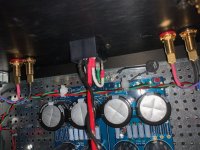
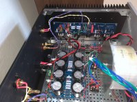
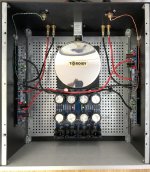
With the very gracious help of Jim and Greg (and with emotional support via Patrick) I was able to get the amp biased. I have run into yet another problem: this time it is hum. I'm guessing something isn't grounded correctly since I can hear the transformer hum from about 3 feet away. I don't know what would make a transformer hum that loudly besides very bad grounding. The power board is grounded to the chassis at the same location as the inlet ground, and via a thermistor. When I checked them the screw seemed very tight. The transformer is grounded to the same part of the chassis. Another thought is the something in the power supply isn't wired correctly. This last thought originates from the fact that the safety thermistors at the inlet get so hot at power on that toughing them would result in some very serious burns (like with black skin kind of burns - I forget where this is on NP's scale but I bet someone here knows). What doesn't make sense to me is that the unit powers up and can be biased with about 24vdc coming out of the PSU in each channel (which seems about right for an 18v transformer). Anyone have recommendations on where I start looking? I'd really love to get this amp working correctly after 6 months of crazy...! Was would cause the safety thermistors to heat up so radically (this doesn't happen with my M2x), generate enormous hum in the transformer, and still allow the PSU to supply~24vdc to the amp boards? Please see attached photos. Thanks, /d
Attachments

When you press your ear to the speaker (possibly ground loop) do you hear hum or is it coming from the transformer (mechanical). We need to see your signal input wiring scheme.
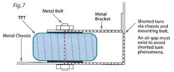
Transformer shorted turn? Make sure the transformer mounting bolt is not touching the front panel.
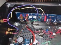
1. The mains voltage wiring is everywhere... needs to be shortened and routed away from all other wirings
2. The speaker wiring runs in parallel with input wiring.
3. Shorten all wiring🙂
4. Hopefully, the transformer mounting bolt is not touching the front aluminium plate😱
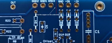
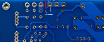
5. Aleph J PCB should be modified before you start any work. I think the PCB should have a provision for this; many DIY-ers spent a serious amount of time chasing the 100 (120) Hz hum.
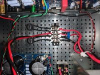
See attached photos; the amp photo will giver you idea how to achieve very short wiring in general. The thermistors can be mounted right on the IEC input block. You'll end up with 10cm-long (max.) mains wiring, very short DC rails wiring, good segregation of input vs. speaker wiring - your ears will like it a lot!
2. The speaker wiring runs in parallel with input wiring.
3. Shorten all wiring🙂
4. Hopefully, the transformer mounting bolt is not touching the front aluminium plate😱
5. Aleph J PCB should be modified before you start any work. I think the PCB should have a provision for this; many DIY-ers spent a serious amount of time chasing the 100 (120) Hz hum.
See attached photos; the amp photo will giver you idea how to achieve very short wiring in general. The thermistors can be mounted right on the IEC input block. You'll end up with 10cm-long (max.) mains wiring, very short DC rails wiring, good segregation of input vs. speaker wiring - your ears will like it a lot!
Attachments
Greg,
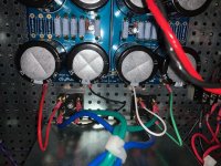
I get hum from both the transformer and the speakers (and of course the crazy thermistor heat). I've tried rerouting the input and output wiring to no avail. Photos attached.
Thanks,
/d
First, lets deal with the mechanical vibration. Do you have the Antek rubber grommet installed?
Ben and EB, no the bolt doesn't touch the front panel. You can see in the photos that the bolt faces in toward the inside of the case.
EB, the wiring was changed from my original to test how the configuration alters the transformer hum, which in my mind is the larger issue. The wiring length and location has no impact so far on the transformer hum. I can always shorten the wires later and your point is well taken.
Greg, yes, there are rubber washers on either side of the transformer. The setup here follows Jim's fairly closely in his example. Or, at least I tried to. I was more successful in my M2x build, apparently, which uses the same setup. I've compared the two builds and it is either something super obvious or not since I'm not finding the difference. I'm still really concerned about the extreme thermistor heat and am guessing a clue is hidden there....
Thanks,
/d
Do you have a second transformer that you can sub in to rule out an inherently loud transformer? (I have heard this can happen). Have you tried flipping it so the side that faces front now, faces the case interior? And also rotating it, listening for the optimal/quietest position—yes requires loosening it just so, and rotating it with the amp on. I have found that generally I end up with the secondaries around 12 o'clock and primaries on the bottom with an L mounted toroid... each amp/donut has been a little different—but each of them had an optimal "most quiet" position—and it was NOT subtle. Also try routing the mains under the baseplate as short as possible—made all the difference in my F5—before I blew it up (As an aside that amp is quite ghostly quiet, after major revisions thanks to Jim and Zen Mod, and the Antek I used did not have a shield/purple wire).
When building M2X mono blocks I hooked up earbuds directly to the speaker outputs to listen to what made what more quiet. Ferrite core on the primaries made a difference as did toroid rotation "tuning" (and mumetal shields on the autoformers—specific to M2 of course). Also make sure the transformer isn't sitting/touching on the bottom of the L bracket.
My AJ is louder than my M2X mono blocks—but I don't think that is "right" (on the list to diagnose)—and I did the HBR cut trace mod that's been mentioned many times—So I feel your pain—it's a fantastic amp.
Also try some seriously weenie input wires. Like 30awg. I had some mogami shielded input wires in my first round AJ—where the shield was ground—and for whatever reason they were LOUD, IDK.
Extreme_Boky's amp interior shot is a thing of beauty! I haven't tried the PSU oriented like that with the diode bridge far away from the toroid—will have to try that—WISH we could get those toroidy beauties for less here in the US. Just gorgeous.
Lastly, try getting busy on this page:
Ground Loops
Specifically the PDF on the page called "Ground-Loops". It's audio GOLD.
Last edited:
Antek purple is connected to the perforated baseplate visible in the last photo of post 5142. It’s fine. (Always a good question, btw...)
What do you mean by safety thermistors? If you are referring to the two thermistors in series with the transformer primaries, they are for soft start. They are approximately 10 ohm or so when cold, and they heat up as current flows through them and that reduces their resistance. They do operate hot.
A loudly humming transformer is not normal. That is why I thought shorted turn. Is it also hot? You mentioned that the bolt points towards the inside of the case. However, the bolt has two ends. The opposite end of the bolt and the steel plate on the opposite side must not touch the front panel of the case.
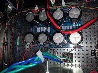
Another thing to check is for accidental shorts. With the AC cord unplugged, take you meter and check for shorts between the chassis and power supply and amplifier boards. It is hard to see but it appears to me that the standoffs for the power supply board and the amplifier boards are fairly short. Perhaps there is a wire on the back side of a board touching the chassis.
If you do not spot anything out of place, the best strategy is to disconnect both amplifier boards and test the power supply alone. Does the transformer hum with no load? Measure V+ and V-.
If the power supply checks out, connect one amplifier board at a time and check each one individually.
A top view showing the whole amplifier for an overall view would also be informative.
A loudly humming transformer is not normal. That is why I thought shorted turn. Is it also hot? You mentioned that the bolt points towards the inside of the case. However, the bolt has two ends. The opposite end of the bolt and the steel plate on the opposite side must not touch the front panel of the case.
Another thing to check is for accidental shorts. With the AC cord unplugged, take you meter and check for shorts between the chassis and power supply and amplifier boards. It is hard to see but it appears to me that the standoffs for the power supply board and the amplifier boards are fairly short. Perhaps there is a wire on the back side of a board touching the chassis.
If you do not spot anything out of place, the best strategy is to disconnect both amplifier boards and test the power supply alone. Does the transformer hum with no load? Measure V+ and V-.
If the power supply checks out, connect one amplifier board at a time and check each one individually.
A top view showing the whole amplifier for an overall view would also be informative.
Pfarrell, no extra transformer without pulling apart my M2x. I don’t think it is a good idea to take apart something that is working, but I can if needed. I have not tried changing the position of the transformer. I will look into that and the ground loop. I will PM you later about reducing noise in my M2x. Gotta get this fixed first. Thanks for the help.
Further suggestions re correct grounding. Easy to digest...
note: Papa's amps have speaker returns fed straight to the PS boards.
https://www.circuitbasics.com/wp-co...er-With-an-LM3886-Master-Wiring-Diagram-4.png
note: Papa's amps have speaker returns fed straight to the PS boards.
https://www.circuitbasics.com/wp-co...er-With-an-LM3886-Master-Wiring-Diagram-4.png
Attachments
Ben, I don’t think the thermistors should ever get this hot. I will measure the temp and post it. My M2x thermistors don’t even get warm and the PSU is exactly the same. I’m not sure what a shorted turn is and how to identify one. If you let me know I’ll check. Neither end of the bolt touches the chassis. I will check for shorts, but I’ve done this already looking for problems with the amplifier boards previously. You can see my previous posts about those problems. I have posted the amp previously, but will post it again. I will test the PSU separately, but I’ve done this previously, too. I will repeat and post again. Thanks
A shorted turn in a toroid transformer is when there is a closed winding around the toroid. The closed winding can be formed by a central bolt in contact with the front of the case and in contact with transformer mount, and then continuous through the case bottom plate to the front panel. However, if you have a gap between your transformer mounting bolt and plate and the front panel, then you don't have a shorted turn.
See attached image for an example of a shorted turn. Note that all that is needed is electrical contact. Bolting to the front panel is not necessary for a shorted turn to occur.
If the thermistors are hotter than usual, it could be because they are passing more current than normal. The thermistors should be quite hot though. They usually get hot enough that you cannot touch them continuously.
Again, if you cannot determine why your transformer is humming, a methodical approach is best as mentioned in my previous post.
Attachments
Last edited:
What I would try:
Does the transformer mechanical hum when
- secundary disconnected (no load) -> yes? Could be DC on AC mains line.
- connect only diode bridge, still ok?
- add the rest of psu board caps.. still ok?
- connect 1 channel
Does the transformer mechanical hum when
- secundary disconnected (no load) -> yes? Could be DC on AC mains line.
- connect only diode bridge, still ok?
- add the rest of psu board caps.. still ok?
- connect 1 channel
What I would try:
Does the transformer mechanical hum when
- secundary disconnected (no load) -> yes? Could be DC on AC mains line.
- connect only diode bridge, still ok?
- add the rest of psu board caps.. still ok?
- connect 1 channel
+1
Try to be systematic in figuring out the mechanical hum first. Mechanical hum indicates that something is very wrong, either with the load or with the transformer itself.
Have you disconnected your interconnects to see if the hum stops? Sorry if this has already been asked or accomplished.
- Home
- Amplifiers
- Pass Labs
- Aleph J illustrated build guide