Spoon boy: Do not try and bend the spoon. That's impossible. Instead... only try to realize the truth: you can not improve on perfection🙂
DIY-ers: hear hear.
DIY-ers: hear hear.
There is an intermediate solution for providing more independent power to the channel boards. Given a transformer of sufficient VA rating, one can use a shared set of bridge rectifiers & first bank of capacitors. The second bank of caps are duplicated for each channel and powered through independent resistors. This is documented in the F6 article, and also appears to be the approach used in the XA25.
If you have a nice set of four oil-filled motor run caps, it is easy to try a limited version of this concept by connecting the motor run caps separately to each channel board.
If you have a nice set of four oil-filled motor run caps, it is easy to try a limited version of this concept by connecting the motor run caps separately to each channel board.

There is an intermediate solution for providing more independent power to the channel boards. Given a transformer of sufficient VA rating, one can use a shared set of bridge rectifiers & first bank of capacitors. The second bank of caps are duplicated for each channel and powered through independent resistors. This is documented in the F6 article, and also appears to be the approach used in the XA25.
If you have a nice set of four oil-filled motor run caps, it is easy to try a limited version of this concept by connecting the motor run caps separately to each channel board.
I like this idea very much, and is something I could implement quite easily as I have more of these big electrolytics and dozens of the motor run caps. The xfmr is plenty large enough, I think 8 amps. I would just need to dismantle it again and back to the shop for some drill press time.
Thanks, it's a great idea.
Cheers
Increase bias = increase 2nd harmonic & decrease 3rd?
I've been having some fun with this circuit in LTSpice in preparation for an upcoming build. I thought that it would be fun to up the bias to boost performance into difficult loads.
However, upping the bias from just under 0.9 A to a little over 1A results in a 4 dB increase in H2 and a 2 dB decrease in H3. I've fiddled with the AC gain feedback resistors, and if I drop the AC gain to about 30%, I can match H2 and H3 at a higher bias level, but that's unhelpful - more heat for the same performance. I've experimented with methods of changing bias (e.g., lower value source resistors and adjusting R27), but the trend is consistent.
There is a sweet spot, it seems. Low bias - around 0.6 A - performs much worse than the specified value of about 0.85 A or so. It obviously makes sense that NP would select an appropriate bias point for the design as published, but I'm wondering why the performance suffers as you try to scale it up.
Any thoughts on why this may be so? It would seem as if the distortion should decrease across the board with increasing bias: http://www.firstwatt.com/pdf/art_mos_test.pdf
Am I missing some adjustment that should be made to compensate?
well , it is something there ........ just to show you that you really need to investigate the same in vivo
you really need to investigate the same in vivo
I just ran the sims using Cordell's IRFP240 model instead of the model bundled with LTSpice, and the distortion difference between low and high bias vanished. You're right - it appears to be an artifact of simulation/modelling.
I remember that I adjusted the trim-pots as per Nelson's Alph J schematics: R8 was a 1K resistor, R7 a 2K trim-pot adjusted for 1K; R27 a 100K trim-pot adjusted for 68.2K. The quiescent current was around 0.56V / 0.47 ohms = 1.2A per each "branch". I am not sure what the quiescent current was in an FW production Aleph J...
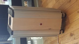
Spare Dumpster Heatsinks
I've got some great heatsinks for this project, I'm using two of them but I've got two spares.
I've got some great heatsinks for this project, I'm using two of them but I've got two spares.
Attachments
Last edited:
I remember that I adjusted the trim-pots as per Nelson's Alph J schematics: R8 was a 1K resistor, R7 a 2K trim-pot adjusted for 1K; R27 a 100K trim-pot adjusted for 68.2K. The quiescent current was around 0.56V / 0.47 ohms = 1.2A per each "branch". I am not sure what the quiescent current was in an FW production Aleph J...
The Factory Manual says peak current output is 2.5 A. With 42% AC gain, which is approximately the AC gain of the posted schematic, 42% of the output current comes from the variation of the current source, or about 1 A. That leaves 1.5 A to be provided by the gain devices, requiring at least 0.75 A bias on each.
In simulation, if I hook up R27 as in the original schematic, I get around 1.2 A, like you describe. This would pump out much more than 2.5 A current at peak, though. Dissipation would be about 220 W, which squares with the manual’s statement of “about 200 watts.” Maybe the current output of the factory model is substantially derated?
In this build guide, 0.85 A is suggested, and this comports with a peak 2.5 A plus a little buffer. I get about .9 A if R27 is connected at the junction of R25 and R26, as it is in the Aleph X and Babelfish J. There was some question about if the Aleph J schematic was correct and where R27 should be connected but I didn’t find an answer.
This post suggests that the latter connection is more typical of Aleph amps. Stated in reference to the Aleph 5:
Yes, you can increase the bias easily enough using the resistor which feeds the Base of the NPN transistor on the positive current source. I forget the number, but its the one which goes from the Base to a capacitor which is charged by a resistor to the positive supply.
Last edited:
Wowbagger, very interesting discussion, I'm intrigued by the changes made my moving R27 to where Nelson seemed to indicate it should go.
I'm going to do a little research as well.
In your reference to idle current and dissipation, are talking about total per channel or per IRFP240? As I am using a single IRFP150 my current measurement is total per rail/channel and right now it's set at 1.9A total and results in 210W draw from the AC line for 2 channels. If you are implying 1.2A per device then that is doublethe original design, WOW!
Looking forward to further discussion.
Cheers
post schematic showing different positions of "disputable" resistor , so we can comment
I remember some debate about , but also remember there was no issue per se , difference being of academic , not practical relevance
I remember some debate about , but also remember there was no issue per se , difference being of academic , not practical relevance
In your reference to idle current and dissipation, are talking about total per channel or per IRFP240?
The numbers are per device, except for the peak output of 2.5 A, which is total, and the 220 W dissipation, which is for all 8 devices in the stereo amp. The actual draw would likely be a bit higher.
Last edited:
difference being of academic , not practical relevance
The difference in practice may be academic, as the bias can be controlled with either arrangement, but it's just a question of what was the originally intended bias. Moving the connection but keeping the value - 68.2k - results in the different bias values I mentioned.
Here's the first question I saw about how it should be arranged:
Hello Papa
Refering to your Aleph J schematic, R27 is connected directly to the gate of Q5 and Q6.
Is it possible that R27 is intended to be connected between the junction of R25, R26 and C2? If connected this way it results in 2A bias and seems to operate somewhat better into low impedance loads (from memory).
The way you have it connected results in approximately 2.6A of static bias (a little high).
I know the issue of high bias was addressed by members with trimpots, but it was applied somewhat differently.
It seems to me R27 should have been connected between R25, R26, and C2

I was meant to ask this question approximately 8 years ago. Back then I was a scaredy cat. 😀
Reply:
I asked
Pa replied ........ naah , it's not so important
meaning - bugger off , who cares for little details already chewed zillion times

Last edited:
post schematic showing different positions of "disputable" resistor , so we can comment
I remember some debate about , but also remember there was no issue per se , difference being of academic , not practical relevance
Top junction of R27.
Attachments
The Factory Manual says peak current output is 2.5 A. With 42% AC gain, which is approximately the AC gain of the posted schematic, 42% of the output current comes from the variation of the current source, or about 1 A. That leaves 1.5 A to be provided by the gain devices, requiring at least 0.75 A bias on each.
In simulation, if I hook up R27 as in the original schematic, I get around 1.2 A, like you describe. This would pump out much more than 2.5 A current at peak, though. Dissipation would be about 220 W, which squares with the manual’s statement of “about 200 watts.” Maybe the current output of the factory model is substantially derated?
I have 5U chassis; 1A quiescent current at the moment, per each branch. I remember I noticed an improvement when I went up, from 0.8A to 1A. The sound was more relaxing and enjoyable. The winter is approaching our hemisphere, so I will go up to 1.2A and see what happens.
Has anyone done the distortions vs. the quiscent current measurements on a real Aleph J?
Jim has some pictures of a few current / distortion measurements on the first page of this thread.
Remember that “bias” in the Aleph is actually AC current gain, although increasing it does increase the total current and therefore bias. Generally speaking you are hearing the change in the current gain instead of the actual bias, as it has a more direct effect on distortion spectra.
Also speaking in generalities, Nelson’s suggested settings are almost always in the “sweet spot” for subjective sound quality. However, it’s absolutely up to you to experiment and find out what you like best. 🙂 🙂 🙂
Also speaking in generalities, Nelson’s suggested settings are almost always in the “sweet spot” for subjective sound quality. However, it’s absolutely up to you to experiment and find out what you like best. 🙂 🙂 🙂
- Home
- Amplifiers
- Pass Labs
- Aleph J illustrated build guide