Well done.
There are a few more things you could do to further reduce the buzz.... and improve the sound.
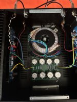
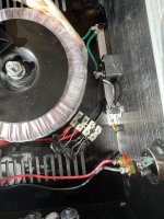
Swap the PS PCB and the transformer around.... the mains wiring is waaaay too long.
Place the input hook-up loom right next to the heatsink... (push the hook-up wiring close to/against the heatsinks)... you may have to replace the loom with a slightly longer one.
Install two chokes instead of 4 x 0.47ohm/3W resistors... on the PS PCB <- this will kill the buzz completely:
https://au.mouser.com/ProductDetail...=sGAEpiMZZMv126LJFLh8y6KZKfL7WqIIQO5I0w1QYO4=
There are a few more things you could do to further reduce the buzz.... and improve the sound.
Swap the PS PCB and the transformer around.... the mains wiring is waaaay too long.
Place the input hook-up loom right next to the heatsink... (push the hook-up wiring close to/against the heatsinks)... you may have to replace the loom with a slightly longer one.
Install two chokes instead of 4 x 0.47ohm/3W resistors... on the PS PCB <- this will kill the buzz completely:
https://au.mouser.com/ProductDetail...=sGAEpiMZZMv126LJFLh8y6KZKfL7WqIIQO5I0w1QYO4=
so the chokes would take the place of the 4 resistors per side on the cap board? How would I connect that? Also could you recommend a power switch and a way to control a power led. Not sure how to do that but I think it involves a diode so the led won't burn out. Would swapping the ps board and the transformer make a big difference in the performance of the aleph?
Last edited:
Yes, you'll need to remove the resistorsso the chokes would take the place of the 4 resistors per side on the cap board?
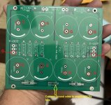
At the PS PCB underside, as per this photo... scrape the lacquer - this is where you'll solder the choke wires, use 80W soldering iron. You will also need to solder 16 little solid core pieces of copper wire, where the resistors used to be (through the eyelets/holes)... this will ensure good electrical conductivity between two PCB layers... we're talking about a 4A constant current run here...How would I connect that?
Can you use the AMP PCB diodes... just relocate them where you need them... and choose the appropriate colour... or use a rocker switch with a bulb (the bulb brightness will diminish over time...)Also could you recommend a power switch and a way to control a power led. Not sure how to do that but I think it involves a diode so the led won't burn out.
Yes, the mains wiring length will be drastically reduced.Would swapping the ps board and the transformer make a big difference in the performance of the aleph?
Last edited:
As always, I am late to see OP's post regarding hum.
I had the same experienced with the same board when I built the Aleph J. Of course, when I had the PSU board powering the F4, no hum (as no V gain) even with 99dB speakers.
My episode started here https://www.diyaudio.com/community/threads/aleph-j-illustrated-build-guide.241729/post-7269676
I ended up moving the audio input wires to the side and replacing the PSU as the solution shown here https://www.diyaudio.com/community/threads/aleph-j-illustrated-build-guide.241729/post-7271046 for hum free operation.
But I got curious on why the PSU board hums. To make a long story short, I found out hum free operation using the PSU board by:
I was really going to try 20 ohms 15W resistor as CL 80 replacement to experiment if it is the right number but concluded F it, I am done! In the end, I just use the diyaudio store PSU and live happily hum free after.
I had the same experienced with the same board when I built the Aleph J. Of course, when I had the PSU board powering the F4, no hum (as no V gain) even with 99dB speakers.
My episode started here https://www.diyaudio.com/community/threads/aleph-j-illustrated-build-guide.241729/post-7269676
I ended up moving the audio input wires to the side and replacing the PSU as the solution shown here https://www.diyaudio.com/community/threads/aleph-j-illustrated-build-guide.241729/post-7271046 for hum free operation.
But I got curious on why the PSU board hums. To make a long story short, I found out hum free operation using the PSU board by:
- Nylon standoffs so that there's only one connection to chassis ground (after the RTC), avoiding any connection to chassis from the corners.
- Since RTC is the only connection of the board to the chassis floor, RTC is acting as a ground breaker resistor.
- RTC end then connects to where the chassis ground plane and IEC ground wire meets.
- IEC Ground connection to the shortest possible path to chassis.
- And lastly, I used CL-80 (47 ohms) instead of CL-60 (10 ohms).
I was really going to try 20 ohms 15W resistor as CL 80 replacement to experiment if it is the right number but concluded F it, I am done! In the end, I just use the diyaudio store PSU and live happily hum free after.
Last edited:
well, maybe not so well done. my left channel just started distorting any recommendations would be appreciated. gosh darn, it! got rid of 1 problem but ended up with anotherWell done!
I think I blew a MOSFET...maybe I mishandled the driver board when taking it apart to do the mods?
I'm glad I have spare mosfets and jfets. I purchased 2 of the kits from the Diyaudio store........I would prefer not to do a blanket replacement and try to isolate the problem.
Start with the most basic checks... disconnect the AMP PCBs and confirm that you are getting + and - (20-25V) on the PS PCB.
If all is good with the above measurements, then:
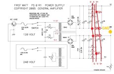
1. Print the attached photo - a couple of copies.
2. Connect the good working AMP PCB and measure the voltages as per the arrows shown... Write them down.
3, Disconnect the good working AMP PCB.
4. Connect the faulty AMP PCB and measure the voltages as per the arrows. Write them down.
5. Scan both sheets of paper and post them here so that we can try to figure out what's going on...
The measurements should be taken without any load attached to AMP PCBs.
Good luck.

If all is good with the above measurements, then:
1. Print the attached photo - a couple of copies.
2. Connect the good working AMP PCB and measure the voltages as per the arrows shown... Write them down.
3, Disconnect the good working AMP PCB.
4. Connect the faulty AMP PCB and measure the voltages as per the arrows. Write them down.
5. Scan both sheets of paper and post them here so that we can try to figure out what's going on...
The measurements should be taken without any load attached to AMP PCBs.
Good luck.
Last edited:
Ok. I may be having an intermittent problem. the amp is currently working with no faults. let's see how long it takes to come back . I may be having a thermal problem. I will reset the bias and offset, get the thing nice and toasty, and report back.
Go over your soldering joints with a hot iron. Sounds to me like bad connection. Not that uncommon.
If you are still experiencing hum, in post #45, image 1, can you please try to move the red/blk wires (DC with ripple) from the green and blue wires (AC) from the bundle? If you do and touch it, does the hum loudness change? If so, you have coupling. I suggest to twist the corresponding blue and green wires together for each trafo output, then twist the corresponding red/blk from rectifier to board on each. Try to minimize loop areas if you can. Here's to hoping that you will have a hum free amp operation soon!
The Grounding issue with this power supply board is that the Ground output is located in the middle of the C R C filter, not at the end of the C R C filter.
The V+ and V- outputs could be better positioned too.
The power is cleaner if all of the outputs are located at the end of the CRC filter.
The V+ and V- outputs could be better positioned too.
The power is cleaner if all of the outputs are located at the end of the CRC filter.
Attachments

Hello,Extreme Bolky, its my fricken tube cd player that went out.😳 I swapped it out with another player and all is good. I do want to ask if the resistor mod for the hum will have any effects on the sound quality? what forum should I post to try to get some help with my tube cd player lol
- Home
- Amplifiers
- Pass Labs
- Aleph J hum