I say that you can go a bit higher for the case temp, like 70-75 maybe. It's just me though 🙂
75C is 167F - That will burn you.
Plus if your heatsinks are that hot, your transistors are getting really hot, and that's just not a good idea.
The max you want to have is 65C transistors, 55C heatsinks
Oh, I was talking about the transistors case, 2nd leg if you like. You are not going to touch it too often 🙂
I checked the temps this afternoon and had the following readings:-
Heatsinks 43C Mosfet cases 47C
Source resistor are at 53C whilst the schottky diodes are running at 56C.I think I'll fit bigger sinks on the schottkies or perhaps fit standard bridges or do folks think that 56C is out of the way?
Heatsinks 43C Mosfet cases 47C
Source resistor are at 53C whilst the schottky diodes are running at 56C.I think I'll fit bigger sinks on the schottkies or perhaps fit standard bridges or do folks think that 56C is out of the way?
Look at the temperature ratings for the diodes you are using. (on the datasheet) My guess is that they are fine. Heatsinks never hurt, however...
Also - please take some photos of your amp and post them in the build guide thread!! 🙂 🙂 🙂
Also - please take some photos of your amp and post them in the build guide thread!! 🙂 🙂 🙂
Thanks Jim I'll post pics at some point but need to treat myself to a new camera first.
Forgot to say the diodes already have small sinks fitted.
Forgot to say the diodes already have small sinks fitted.
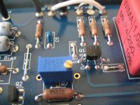
I want to give some feedback about the bias adjustment of my aleph J with lateral toshibas.
At the end i have got R27=14.3K, R8=2k and R7=0.16K
Voltage drop near 450mV across the source resistors and offset below 1mV, after 1 hour.
So it was not necessary to change the source resistors, but bias is only adjustable with R27 and not with R8.
It was clear that the sound was getting a bit grainy with bias at 400mV.
The temperatur of the heatsinks is still high, but acceptable.
I like the sound being more relaxed and a bit nicer in the high frequency range than my Alephs with IRF mosfet input and output.
The comparison with F5 have to wait until i got an new Bass chassis for my Harbeth Monitor 30.1
There was a 2SJ109 dying at my first try of the amp, resulting in full voltage at the output, burning the chassis.
Its the first time in like 17 years of amplifier building and my punishment will be a huge bill.
I using my old self made speakers now, they sound nice and involving, but need more damping for the low frequencies and anyway, the Aleph J was planned to check out if it would sound even nicer with the harbeth, than the F5.
I was happy with the F5, but you know sometimes you just have to build something, driven by curiosity.
It was clear that the sound was getting a bit grainy with bias at 400mV.
The temperatur of the heatsinks is still high, but acceptable.
I like the sound being more relaxed and a bit nicer in the high frequency range than my Alephs with IRF mosfet input and output.
The comparison with F5 have to wait until i got an new Bass chassis for my Harbeth Monitor 30.1
I was happy with the F5, but you know sometimes you just have to build something, driven by curiosity.
Thanks for the report. I love to see someone experimenting, traveling their own road. Enjoy.
everything is pretty OK
after some time of enjoyment , check AC gain of Aleph CCS
Thanks Zen;how do I check AC gain?
easy
http://www.diyaudio.com/forums/pass-labs/38033-proper-current-source-adjustment.html#post438837
http://www.diyaudio.com/forums/pass-labs/38033-proper-current-source-adjustment.html#post438837
I'm not sure that the quote addresses the question. I
interpret it as wanting to know how to set the current
gain of the Aleph current source, not the DC bias.
For the former, you generally want to set the gain so that
the AC variation of the current source is about 1/2 the output
current. It can be more or less, but 50% gives the optimal
energy efficiency figure.
You will note in the Aleph schematics that the Base of the NPN
transistor which controls the current source attaches to the
output of the amplifier through an RC network. The value for
C is set arbitrarily high so that it does not interfere with audio
frequencies, and it is the value of R which is the most convenient
spot to adjust the gain of the current source. For the purpose
of this discussion, I'll call it R0.
If you set the amplifier driving a sine wave into a load (let's say
16 Vrms into 8 ohms at 100 Hz), you can measure the current
variation of the gain N channel Mosfets (whose Sources attach
through power resistors to the - supply rail) with a cheap AC
voltmeter placed across one of these Source resistors. With
R0 taken out of the circuit, you will get one AC value across the
Source resistor (say 470 mV, for example). As you put a value
for R0 in the circuit, this will decline, and when it measures 1/2
the value without R0, you have reached 50%. If it measures
1/4 the value, the current gain of the Aleph source is 75%, and
this figure is too high for a standard Aleph. Most listeners like
the Alephs at 50% or lower, so I recommend between 50% and
100% of the AC voltage value compared with no R0.
😎
Last edited:
Signal Jenny proggie from net , to give you a sine , cheap DVM to measure/establish some voltage at output ( say 10V) , dummy load ( anything between 4 and 16R) and to measure voltage across lower Rs for open/closed R0
voltage measurement only need to be relative , not absolute , so DVM doesn't need to be of lab quality
so , you have it all 😉
aha - Signal Jenny : https://dl.dropboxusercontent.com/u/20665608/SigJenny.zip
R0 is R24 here :
(you need to measure voltage across R18 or R19)
edit : my Paesano Logic is telling me that you're at 50% AC gain when AC voltages are same across ,say, R19 and R17 ......... but I'm never sure how's my brain working ...... biz as usual - Mighty ZM in constant state of Public Disgrace
Last edited:
Does anyone know if PD's aleph J boards will fit the UMS?
I have some which I started to populate, they need a case now though and the diya ones look to fit the bill. I know I could just fly lead them off the board, but if they boards fit it's perfect.
I have some which I started to populate, they need a case now though and the diya ones look to fit the bill. I know I could just fly lead them off the board, but if they boards fit it's perfect.
The Peter Daniel boards don't even come close to fitting the UMS.
However, you could drill and tap a few holes and mount them, with or without the fly leads. The spacing on the UMS is pretty large, so you wouldn't interrupt any of the existing holes, and the UMS would be able to be used for future projects.
However, you could drill and tap a few holes and mount them, with or without the fly leads. The spacing on the UMS is pretty large, so you wouldn't interrupt any of the existing holes, and the UMS would be able to be used for future projects.
Ok, thanks. Will put some more thought into it. It may be worth getting the diya boards just for the simplicity. I don't have many components fitted to the pd board, so the replacement part cost would be worth it compared to the hassle of pulling the tap set out. 🙂
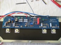
Finished my Aleph J...
I built it in my F5 chassis which wasn't a big trouble because of the UMS specification, and the 24 volt needed for almost all Firstwatt amps.
For the F5, I used a 3 U hifi2000 chassis which isn't big enough for the Aleph J.
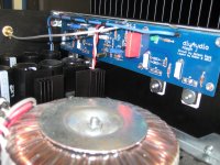
I can bias the Aleph cold at 400 mV over the 0.47 Ohm source resistors which results in 55C heatsinks with the lid off !
The amp seems very robust, bias lowers from 400 mV to 380 mV when warming up. So it bias itself lower when heating up!! That's not the way a F5T reacts 😛
Offset is very stable within a few millivolts. A nice stable and complete Amp. I left out the current limiting.
I have been listening and comparing the Aleph J against the F5Tv3 for a week.
Aleph J wins in the highs and mid highs... what a detail, best I ever heard. Hi hats, cymbals, electronic music..WOW
But the F5Tv3 wins with bigger soundstage...the Aleph J seems more compact.
There is no real winner, both amps sound different, even my wife noticed 😀 but they are both great !
Next is to build the Aleph in his own chassis, I'm thinking of a easy, compact, nice computer case with ( very silent) forced air cooling 😱
Like the cases of Streacom, Fractal Design and Lian Li ...
And of course, as always...here are the pictures... 🙂
Thanks of course to Mr. Pass 😎 and Jim (6L6) for his great Aleph J kit and building guides!
Last picture is the Pass Trio...😀
Walter
I built it in my F5 chassis which wasn't a big trouble because of the UMS specification, and the 24 volt needed for almost all Firstwatt amps.
For the F5, I used a 3 U hifi2000 chassis which isn't big enough for the Aleph J.
I can bias the Aleph cold at 400 mV over the 0.47 Ohm source resistors which results in 55C heatsinks with the lid off !
The amp seems very robust, bias lowers from 400 mV to 380 mV when warming up. So it bias itself lower when heating up!! That's not the way a F5T reacts 😛
Offset is very stable within a few millivolts. A nice stable and complete Amp. I left out the current limiting.
I have been listening and comparing the Aleph J against the F5Tv3 for a week.
Aleph J wins in the highs and mid highs... what a detail, best I ever heard. Hi hats, cymbals, electronic music..WOW
But the F5Tv3 wins with bigger soundstage...the Aleph J seems more compact.
There is no real winner, both amps sound different, even my wife noticed 😀 but they are both great !
Next is to build the Aleph in his own chassis, I'm thinking of a easy, compact, nice computer case with ( very silent) forced air cooling 😱
Like the cases of Streacom, Fractal Design and Lian Li ...
And of course, as always...here are the pictures... 🙂
Thanks of course to Mr. Pass 😎 and Jim (6L6) for his great Aleph J kit and building guides!
Last picture is the Pass Trio...😀
Walter
Attachments
-
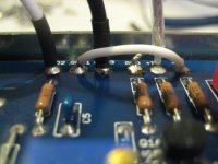 1-negative input to ground.jpg451.5 KB · Views: 580
 -
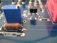 2- 2SJ108 coupled.jpg402.7 KB · Views: 549
 -
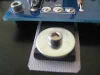 3- Kerafol.jpg425.9 KB · Views: 536
 -
 4- overview.jpg450.7 KB · Views: 545
 -
 5- complete Aleph J missing one jumper.jpg399.5 KB · Views: 381
 -
 6- inside.jpg359 KB · Views: 383
 -
 7- sideview in F5 case.jpg358 KB · Views: 413
 -
 8- inside front.jpg293.9 KB · Views: 411
 -
 9- Pass Trio.jpg254.1 KB · Views: 370
- Home
- Amplifiers
- Pass Labs
- Aleph J for Universal Mounting Spec