This is a thread to discuss the Aleph J PCB on the Universal Mounting Scheme from the DIYaudio store.
Link to UMS - http://www.diyaudio.com/forums/imag...sal/universal-mounting-specification-v2.1.pdf
Link to UMS - http://www.diyaudio.com/forums/imag...sal/universal-mounting-specification-v2.1.pdf
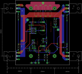
6l6 said:As for the board, I was envisioning the same basic layout as the F4, F5c, etc... The longer board with the outputs all on the lower edge.
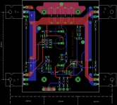
Also, I would love to see R7 replaced with a trimmer pot, as that's where you will be able to dial out any DC offset on the outputs... Maybe put pads for a parallel resistor there as well...
J109's are basically impossible to get anymore, so most people will be using a matched pair of J74's... it would be handy if they were face to face so their cases can be zip-tied together for better thermal tracking.
GKU said:May I suggest some additional design proposals:
- Lead pitch for the use of 1/4W audiophil resistors as Dale or PRP
- Space for an - input foil capacitor as f.i. 1uF ClarityCaps PWA or ESA
Didiet - That looks very nice!
How much lead spacing is there for the 'small' resistors? It would be nice to fit a PRP or dale RN60, as those are about as big as most 'audiophile' resistors. Some people will want to use them.
Great to see the pair of J74 - could you put a pot at R7 as a variable resistor?
If possible, the 0v traces should be bigger, and another wire pad added near the input to connect signal ground, psu ground and speaker ground at one place. See the F4 or F5 pcb in the store for an example.
Thank you so very much for your efforts!
why not make it a long board. all outputs on a line. thats what folks want. so they kan make use of the 400mm wide sinks.
I agree! But the 400mm sinks would be more than enough for an Aleph J. The 300mm would be fine.
Last edited:
yes. 400mm was just a option🙂 its the same for 300mm. let's say board lenght of 240mm
and spacing between the to center fets of 120mm (center to center) and 40mm between center and outher fets (center to center) thats 200mm center to center between the outher fets.
and spacing between the to center fets of 120mm (center to center) and 40mm between center and outher fets (center to center) thats 200mm center to center between the outher fets.
So what you are saying is that you would like to see the basic form factor of the cviller F5x boards?
I agree that it's a great idea, as it is the 'standard' form factor for the DIY audio boards. And if someone has a F5c or F4, etc... they could just plug the Aleph J pcb in with minimum trouble.

I agree that it's a great idea, as it is the 'standard' form factor for the DIY audio boards. And if someone has a F5c or F4, etc... they could just plug the Aleph J pcb in with minimum trouble.
i don't remember how the F5X boards look like. but the F5c/F4 style. only with bigger space between the 2 center outputs.
or make it posible to use some standar ouput boards with it. i have the peter daniels board's. but if i want to use them, i need to use output boards from my aleph30 boards. just to get the heat spread over my sinks.
or make it posible to use some standar ouput boards with it. i have the peter daniels board's. but if i want to use them, i need to use output boards from my aleph30 boards. just to get the heat spread over my sinks.
Last edited:
i don't remember how the F5X boards look like. but the F5c/F4 style.
I meant F5c -- sorry.
aha🙂 then we are on the same page🙂
*banging my head* Cviller's F5X. there is no F5x boards from him😀😀 i did not get that the first time😀
and yes. like the F5c boards. only with more space between the 2 inner fets.
*banging my head* Cviller's F5X. there is no F5x boards from him😀😀 i did not get that the first time😀
and yes. like the F5c boards. only with more space between the 2 inner fets.
Last edited:
Didiet - That looks very nice!
How much lead spacing is there for the 'small' resistors? It would be nice to fit a PRP or dale RN60, as those are about as big as most 'audiophile' resistors. Some people will want to use them.
Great to see the pair of J74 - could you put a pot at R7 as a variable resistor?
If possible, the 0v traces should be bigger, and another wire pad added near the input to connect signal ground, psu ground and speaker ground at one place. See the F4 or F5 pcb in the store for an example.
Thank you so very much for your efforts!
Lead spacing for small resistor 10mm. I add pot for R7 and wire pad.
For long board, i'll try to make one.
Didiet
Attachments
yes. like the F5c boards. only with more space between the 2 inner fets.
But still the spacing for the UMS... 😀 😀 😀
yes 6L6. say 120mm between the inner fets. thats fine for UMS🙂 and then 40mm to the outher fets🙂
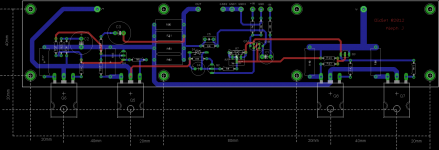
Long board
That looks like a nice package. Where do we sign up for the group buy? 🙂
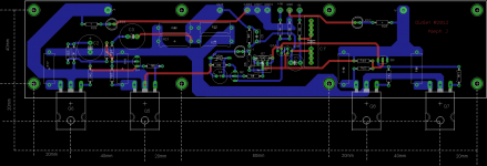
The intent of this board is that it will become the one sold in the DIYaudio store -- Hence the UMS and a few other tweaks.
A question for those smarter than me - (of whom there are many!)
?Does the entire amp see ground through R2??? It looks that way on the schematic, and on this board...
Regardless, the trace between the GND pads and R2 need to be thicker.
And if you could entertain another request, I would love to see an LED on each rail, so you can see at a glance that the amp board is powered correctly. 🙂
- Home
- Amplifiers
- Pass Labs
- Aleph J for Universal Mounting Spec