Good things are coming out of this: I learned how to match JFETs and MOSFETs. This is my first experience with a kit from diyaudio store; and I think they're of great quality.
Most importantly, I feel a sense of community on this forum. I've been a member for 7 years (since I built a Tubelab SE), but this is the first time I've participated a lot.
When I pull resistors off the board, I'm going to measure every one to see if I made a mistake. I'm not sure how to check capacitors; but I'm sure they were installed with the correct polarity. I'll post what I find if anyone's interested.
Oh, by the way, I checked for continuity with each of the MOSFET pins and the chassis before powering up. To validate this test method, I tested for continuity between the chassis and hold-down screws - and found it. There was none for the MOSFET pins.
I'd love to figure out what I did wrong.
Fantastic. You'll get it. 😀 You know it made music for a little while, but perhaps during the troubleshooting phase with the PSU wiring something went sideways.
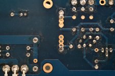
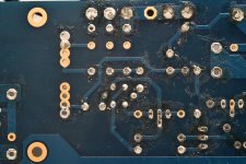
Post one more tight shot of the board in its current state if you haven't already started pulling resistors and other components. As you've seen, there are people with eagle-eyes that can spot anything. Some know all the resistor colors and at a glance know the values. I know this thread moved pretty quickly for me, and I lost track of what was fixed earlier, the current symptoms, and what remains to be solved.
Have fun!
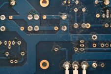
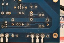
IAIMH: I think only the MOSFETs have changed since the last macro shots.
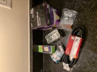
BTW: My Newark order just came. I ordered four of these:
https://www.newark.com/aavid-thermalloy/4180g/thermal-insulator-to-218-to-247/dp/21M5217
They're solid and inexpensive, unlike the other insulators I was using. If they're recommended, I think I'll order them for an other projects that use this packaging.
That link didn't work. Maybe this:
https://www.newark.com/aavid-therma...21m5217&ddkey=https:en-US/Element14_US/search
https://www.newark.com/aavid-therma...21m5217&ddkey=https:en-US/Element14_US/search
They come highly recommended.
Check these out: Aluminum Oxide Ceramic Insulators
$17 will get you 25 of them and with a thin layer of goop on each side, they measure just as good at thermal transfer as Keratherm at $2/each.
I pulled all the resistors (except those for the LEDs), and have found no mistakes.
Yesterday, I ordered enough new parts to build one side. I think they should all be here by Sat.
In the mean time, I'm continuing to validate what I've done.
One of the new parts is a matched *pair* of JFETs. If everything goes well, I guess I'll eventually get the matching quad and replace everything. My focus is to hear stereo sound 🙂
Why do you want to replace the good Jfets you already have? That seems very silly, particular for a differential pair powered from a Constant Current Source... 😀
6L6, I'm not experienced. I'm trying to cover all bases. Honestly, I don't know what I'm doing, and I'm trying anything I can to make this work. If everything I'm pulling out of the board is checking out, what else can it be?
If the components are good then it’s a bad solder joint or two. That’s not uncommon at all on this amp, everything is interdependent on everything else and it only takes one bad connection to make it out of balance.
How do I know? I had that exact thing on one channel of the very first build of this PCB... 😀 😀 😀. Poked around with a wooden chopstick with the meters hoked up to bias and offset and eventually found a spot on the PCB where if it was being pressed/flexed in, things were fine. Resoldered that connection and had zero problem since.
How do I know? I had that exact thing on one channel of the very first build of this PCB... 😀 😀 😀. Poked around with a wooden chopstick with the meters hoked up to bias and offset and eventually found a spot on the PCB where if it was being pressed/flexed in, things were fine. Resoldered that connection and had zero problem since.
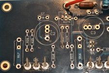
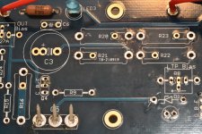
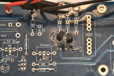
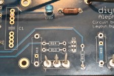
I did re-touch all the solder joints twice. I'm not extraordinarily talented with a soldering iron; but I'm not terrible. It's difficult to imagine three rounds of soldering continued to leave a joint malfunctioning. I'm more suspect of my ability to properly test the components.
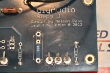
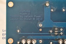
Macro pics before re-stuffing.
Attachments
-
 DSC_2434.jpg894.7 KB · Views: 152
 -
 DSC_2435.jpg900.9 KB · Views: 156
 -
 DSC_2436.jpg903.6 KB · Views: 157
 -
 DSC_2438.jpg880.8 KB · Views: 136
 -
 DSC_2439.jpg887.3 KB · Views: 148
 -
 DSC_2440.jpg896.7 KB · Views: 64
 -
 DSC_2441.jpg864.7 KB · Views: 63
 -
 DSC_2442.jpg893 KB · Views: 64
 -
 DSC_2443.jpg872.9 KB · Views: 58
 -
 DSC_2444.jpg901.9 KB · Views: 66
pre-set those trimpots before powering on
lower one (LTP drain) to 350-400R
upper one (Aleph CCS) to 50K or so
lower one (LTP drain) to 350-400R
upper one (Aleph CCS) to 50K or so
Thanks ZM. I did that, and... ugh. I'm getting the same behavior when I try to dial it in.
I replaced every component except the last set of MOSFETs, the original JFETs, and the LEDs and their resistors.
When I have the replacement JFET's (hopefully tomorrow), I'll give it another go.
I replaced every component except the last set of MOSFETs, the original JFETs, and the LEDs and their resistors.
When I have the replacement JFET's (hopefully tomorrow), I'll give it another go.
All joking aside - it's saved my bacon a number of times.
I'd seriously consider doing one just like this:
F6 Illustrated Build Guide
Since you want to do the F6 too. See the last section of 6L6's first post.
I have a few 100 watt bulbs, but they are getting hard to find. I know it must be incandescent, but are other wattages workable, or other type of incandescent?
Russellc
Sure. Other wattages will work just fine and are encouraged based on the amp or whatever is being "measured". Most of the new bulbs post the "equivalent" wattage. So, try to find bulbs that post the actual wattage. Example - my "40W" bulbs are 29 actual.
Here's a great article.
Powering Your Radio Safely with a Dim-bulb Tester
There are also a bunch of YouTube vids out there.
Best piece of "test" gear I own next to a DMM.
Here's a great article.
Powering Your Radio Safely with a Dim-bulb Tester
There are also a bunch of YouTube vids out there.
Best piece of "test" gear I own next to a DMM.
I have one around here somewhere from my tube days. I've not used it on my Pass clones. I rely on Variac. Requires gentle use, but it meters start to read off, can power back down. Like it with power amps, watch bias, can turn it down as voltage goes up.
It isn't as forgiving as dim bulb, and I have smoked a couple of parts in past. It's a good idea to use one no doubt. I have reached level of comfort with Variac.
Dim bulb very forgiving if miss wire.
Russellc
It isn't as forgiving as dim bulb, and I have smoked a couple of parts in past. It's a good idea to use one no doubt. I have reached level of comfort with Variac.
Dim bulb very forgiving if miss wire.
Russellc
Exactly. 😀 If you have a dead short, like I caused on the Iron Pre, it can save some parts and headaches.
I use both a dim bulb and a Variac, particularly if I'm building a new PSU, change anything about the PSU, unmount and remount boards etc. etc. If I build a new set of amp boards, I use a current / voltage limited DC bench supply or supplies at first - then hook it to the amp PSU and use dim bulb / Variac to gently ease into it.
I use both a dim bulb and a Variac, particularly if I'm building a new PSU, change anything about the PSU, unmount and remount boards etc. etc. If I build a new set of amp boards, I use a current / voltage limited DC bench supply or supplies at first - then hook it to the amp PSU and use dim bulb / Variac to gently ease into it.
- Home
- Amplifiers
- Pass Labs
- Aleph J - First Test Issues / No Sound / Blinking LEDs