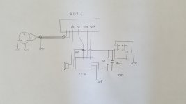
I think something is wrong. When I take the jumper off the input, the speaker voltage jumps from -.1 to +14.5 and starts slowly dropping. The output voltage has never been steady during this procedure.
R18 - 379mv
R19 - 362mv
R16 - 372mv
R17 - 367mv
Thanks again. See you tomorrow.
R18 - 379mv
R19 - 362mv
R16 - 372mv
R17 - 367mv
Thanks again. See you tomorrow.
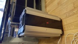
I'll be ready to connect my Aleph Js to the power supply tomorrow.
Attachments
Last edited:
Katie, open your separate thread (or wait), problem of OP isn't yet solved
@ppinto - check again visually - all small transistors pinout/placement
check all jumpers
check all resistor placement
if everything looks ok, remove pcb and triple check all solder joints, renew what looks suspicious and even more
@ppinto - check again visually - all small transistors pinout/placement
check all jumpers
check all resistor placement
if everything looks ok, remove pcb and triple check all solder joints, renew what looks suspicious and even more
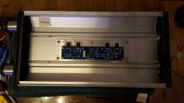
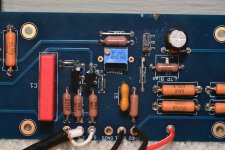
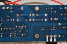
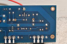
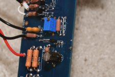
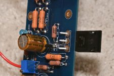
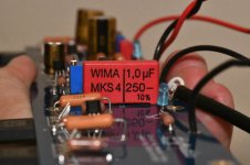
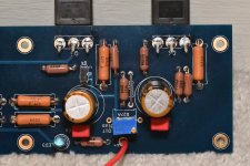
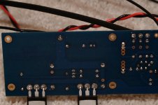
Zen Mod: Thanks for the suggestions. While I do that, I'm providing a set of close-ups for anyone who wants to lend a second set of eyes. There's one more set to follow - along with a question: I couldn't find the exact part number for C1, and I ordered what I think is an equivalent. I don't know if it's the issue here, and I want to cover all bases. It will be the last photo in my next post.
Attachments
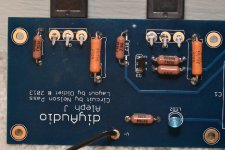
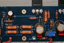

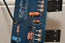
sorta lousy soldering of mosfets
redo that - from top side , crank that solder iron to max and that's the way to do it quick and good
besides that , I can't see anything suspicious
check again orientation of bjt transistors ( small bipolar black ones), recheck value of all resistors - did you put right ones in each position
it seems you got R27 group sorted properly .....
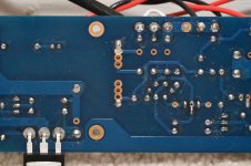
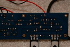
Zen Mod: Thanks for all the suggestions. I have re-soldered every pad (pics attached). I was hoping this was it - so I re-installed the board to test. No dice - output still jumps over +14V when the input jumper is pulled - and R7 can only maintain near 0V within the smallest turn of the pot I can manage (and, it's a 25 turn pot).
I will check the resistor values when I get back from our weekly quarantine shopping. It'll be hours until I can get to it.
In the mean time, do you think it's worth pulling everything out of the board and starting over? I can have an order from Mouser in a couple of days.
I currently have a replacement for R7, and I can start there if it's suspect.
Both of the boards were stuffed at the same time. This was performed by opening a bag of a specific part and populating the same location in either board with the contents. That, along with the fact that this board did achieve proper bias and offset and play music for about half an hour, would tell me it was stuffed correctly and has a bad component somewhere.
For the ~$100 it would cost, I really don't mind. If I go this route, should I also replace the JFETs? If I understand the results of their test, they're good - but I don't mind replacement if they're suspect in any way.
Thanks, again, for your time.
(added) - BTW: I did check the orientation of the ZTX parts.
Attachments
Last edited:
One or more of the mosfets are almost certainly blown. Replace them with the ones Greg is sending you. The passives are going to be fine unless burnt, and there’s no evidence of that.
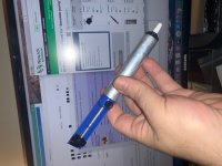
If you don’t have one of these, you’ll find they are very, very helpful.
https://www.newark.com/edsyn/ds017/tools-desoldering/dp/87F1880
If you don’t have one of these, you’ll find they are very, very helpful.
https://www.newark.com/edsyn/ds017/tools-desoldering/dp/87F1880
Last edited:
One or more of the mosfets are almost certainly blown. Replace them with the ones Greg is sending you. The passives are going to be fine unless burnt, and there’s no evidence of that.
If you don’t have one of these, you’ll find they are very, very helpful.
https://www.newark.com/edsyn/ds017/tools-desoldering/dp/87F1880
What is item? I'm just getting opening page of Newark? I could use anything that is helpful!!!
Russellc
6L6 - I think Greg was sending MOSFETs to Freejazz00, but I may have missed him committing another set. If so, awesome!
What part were you recommending? I get their homepage. Always looking for suggestions.
Ppinto1 - I'll scan the boards for any root cause, but ultimately I think 6L6 nailed it. 🙁
What part were you recommending? I get their homepage. Always looking for suggestions.
Ppinto1 - I'll scan the boards for any root cause, but ultimately I think 6L6 nailed it. 🙁
it seems Newark is blocking Sissies from States 
Jim linked "DS017 - Desoldering Pump, Deluxe SOLDAPULLT®, Heavy Duty, PTFE Nozzle, 330mm"
yeah, time for changing mosfets
considering bravery of OP, if things go rough, just cut mosfet legs ditto to pcb , you'll manage easier having free separate pins in holes
Jim linked "DS017 - Desoldering Pump, Deluxe SOLDAPULLT®, Heavy Duty, PTFE Nozzle, 330mm"
yeah, time for changing mosfets
considering bravery of OP, if things go rough, just cut mosfet legs ditto to pcb , you'll manage easier having free separate pins in holes
Bummer on the MOSFET's. That'll be the third set I'm installing in the board. The only place I've found them not on back-order is Newark. I'll order another set when I get back from shopping.
I'll look for a desoldering pump and order that with them!
Zen Mod - that's how I got them out last time - leaving me with 3 good MOSFETs that have no logs 🙂 LOL.
I'll look for a desoldering pump and order that with them!
Zen Mod - that's how I got them out last time - leaving me with 3 good MOSFETs that have no logs 🙂 LOL.
ppinto1 - inspired by the graciousness of Greg, and having just lucked into a score of MOSFETs that had been out of stock for a while. If you'll hold off a day or two for me to match them, I'll send you a set. PM me with your address if that's good for you. I have to go to the PO on Weds to send out some other things.
Definitely love the SoldaPullt! There's a reason all other similar devices are called by the brand name. Kinda like "Kleenex or BandAid".
😀
Edited to add - 1 set of MOSFETs in exchange for a commitment to build and use a dim bulb tester... 3 SETS!? 😀 😀 J/K Have to make light of tough situations.
Definitely love the SoldaPullt! There's a reason all other similar devices are called by the brand name. Kinda like "Kleenex or BandAid".
😀
Edited to add - 1 set of MOSFETs in exchange for a commitment to build and use a dim bulb tester... 3 SETS!? 😀 😀 J/K Have to make light of tough situations.
Last edited:
@ppinto - newark for mosfets?
you know that you need two matched pairs per channel , one pair up, second pair down?
take care of Postman Sniffers
you know that you need two matched pairs per channel , one pair up, second pair down?
......I have to go to the PO on Weeds to send out some other things........
😀
take care of Postman Sniffers

Ooofda (as we say in MN) 😀 Good eyes. eddyvb
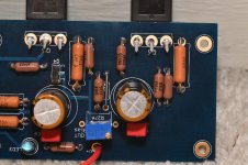
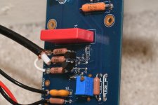
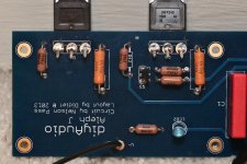
Ppinto1 - Before installing the new MOSFETs, get those swapped to 221R (R11, R12). Looks like 9 and 10 are proper 221R. Now, where'd those other ones go???
Ppinto1 - Before installing the new MOSFETs, get those swapped to 221R (R11, R12). Looks like 9 and 10 are proper 221R. Now, where'd those other ones go???
Looks like they have both "1934J" and "2210F" on them - "1934J" does not fit the resistance code format here (https://www.vishay.com/docs/31027/cmfmil.pdf) since "J" isn't used for the RN60 parts.
2210F fits within the format and corresponds to 221 ohm as specified.
2210F fits within the format and corresponds to 221 ohm as specified.
- Home
- Amplifiers
- Pass Labs
- Aleph J - First Test Issues / No Sound / Blinking LEDs