The Aleph series of amplifiers, First Wall Aleph J, Zen variations 2, 4, 9, my own variation LPTZen and countless other Pass inspired DIY amps all employ the 'aleph' active current source.
The effects of non-linearities in the transfer characteristic of the output transistors can be minimised by operating with high quiescent currents and a limited signal range. With push-pull amplifiers, it helps to ensure that both of the output transistors are driven equally.
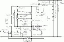
In Zen V4, for example, a quiescent current of 2A is set by using a 0.33 Ohm sense resistor in the drain of the active load transistor. Part of the loudspeaker load current is sampled via a 0.235 Ohm resistor and fed into the base of the current controlling bipolar to modulate the active load current.
The effect of non-linearities in the transfer characteristic of the output transistors can be minimised by operating with high quiescent currents and a limited signal range. With push-pull amplifiers, it helps to ensure that both of the output transistors are driven equally. This is achieved by careful selection of resistor values:
In the case of Zen V4 for example:
R16 = (2 x R14//R15 x R6)/Ro
R16 = (2 x 0.235 x 1k3)/0.33 = 1k85,
( R16 is 1k8 in the first of the attached figures.)
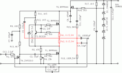
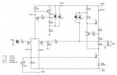
There is a simpler embodiment which eliminates the decoupling capacitor and and loudspeaker current sensing resistor. In the case of Zen V4, open the second attachment.
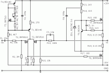
In the case of LTPZen, Aleph J etc open the third attachment.
The effects of non-linearities in the transfer characteristic of the output transistors can be minimised by operating with high quiescent currents and a limited signal range. With push-pull amplifiers, it helps to ensure that both of the output transistors are driven equally.
In Zen V4, for example, a quiescent current of 2A is set by using a 0.33 Ohm sense resistor in the drain of the active load transistor. Part of the loudspeaker load current is sampled via a 0.235 Ohm resistor and fed into the base of the current controlling bipolar to modulate the active load current.
The effect of non-linearities in the transfer characteristic of the output transistors can be minimised by operating with high quiescent currents and a limited signal range. With push-pull amplifiers, it helps to ensure that both of the output transistors are driven equally. This is achieved by careful selection of resistor values:
In the case of Zen V4 for example:
R16 = (2 x R14//R15 x R6)/Ro
R16 = (2 x 0.235 x 1k3)/0.33 = 1k85,
( R16 is 1k8 in the first of the attached figures.)
There is a simpler embodiment which eliminates the decoupling capacitor and and loudspeaker current sensing resistor. In the case of Zen V4, open the second attachment.
In the case of LTPZen, Aleph J etc open the third attachment.
Attachments
Do you refer to this?
http://www.diyaudio.com/forums/pass-labs/37038-excellent-srpp-power-amp-mosfet-4.html#post1982249
I am building a modded Aleph J following this principle.
The fun is that has been posted some years ago but seems to have been unnoticed then. This came under the spotlight when the J2 was born.
Wensan has built a buffer recently, but may be you know the story.
In the Wensan design, there is one more resistor :R16 (Wensan) and no zenner.
What is the zenner for?
It is nice for me to see how to calculate R16 (yours) ...
What do you think about the Zen Mod post
http://www.diyaudio.com/forums/pass-labs/151909-firstwatt-j2-47.html#post2092674
Last edited:
Member
Joined 2009
Paid Member
I have the same the design under construction for an SRPP amplifier - I've seen this embodiment in many places although I don't have a list of references. You might find some related circuits under 'Gyrator' too which show the same thing. I have found that every variation I could think of is there on the Internet, or is a circuit that doesn't work.
Hi Allen,
nice to see you here again 🙂
I like your work very much and I wonder is there any progress on item 4. from your site ?
Cheers!
nice to see you here again 🙂
I like your work very much and I wonder is there any progress on item 4. from your site ?
Cheers!
Hi everyone,
1. Bobodioulasso
Thanks for the link. Wensan's approach is very similar. I searched the posts but missed this one.
I think I have got it about as simple as it can be. I like the fact that it is direct coupled, I like the fact that it is simple and versatile: Should you wish, you can even alter the balance between driver and load simply by adjusting the values of the sense resistors.
I dip in and out of the FirstWatt J2 post. Which particular issue?
Hi Juma
Must get round to posting the preamp details. Thanks for the reminder!
After thinking more about it, i think Zen Mod says it wont work with the low Vgs of power Jfets. (The post I pointed at).
I have seen your website about the zenner clamp...I understand now.
In your third attachment, isn't a resistor missing from collector to base of T9, to set the CS bias?
I have seen your website about the zenner clamp...I understand now.
In your third attachment, isn't a resistor missing from collector to base of T9, to set the CS bias?
It's not that it doesn't work, but you do have to consider the
performance of the npn bias device at lower Vce voltages.
😎
performance of the npn bias device at lower Vce voltages.
😎
T9 doesn't seem to need a bias resistor. I think the 1nF capacitor is sufficient to kickstart the feedback. Thereafter R16 is sufficient.
I could see no reason why you could not substitute the IRFP044n's for jfets, logic level mosfets, darlingtons or even standard bipolars. The feedback controlling bipolar only needs a few milliamps of collector current and at these levels, Vce will saturate at around 30 to 50mV. In fact I have just breadboarded the aleph css (the relevant subcircuit, not the complete amp) using a BC639 for the feedback controller and an old TO3 bipolar of dubious vintage as the current source. With these devices, the collector-emitter voltage of the feedback transistor was measured at ~1.3V and seemed to work fine!
With jfets or mosfets there is no gate current to speak of so you could reduce the collector current below the 5mA or so it currently uses. At the risk of offending some people, nice linear bipolars/darlingtons may worth exploring!
Member
Joined 2009
Paid Member
Allen,
no offense at this end, I like the idea of using bipolars - because I have quite a few in my junk box and no FETs!
I am in the process of building a version of this current source into a simple amplifier with all Bipolars so I'll let you know how it goes (although it's subject of a different thread at this point).
p.s. I like your triac protected psu design, leverages nicely from the cap multiplier.
If you do try it with bipolars or darlingtons, then the positive temperature coefficient may be an issue. With mosfets, the transconductance is degenarative, but with bipolars the HFE is regenerative. Having both output transistors on the same heatsink will no doubt help but you may need to put a capacitor in series with R10 in the 3rd diagram.
The ltp current source is fairly temperature stable and the output drift is minimal with the mosfet output design. Alternatively use a 2nd aleph css on the output driver transistor as per the Aleph amps.
The ltp current source is fairly temperature stable and the output drift is minimal with the mosfet output design. Alternatively use a 2nd aleph css on the output driver transistor as per the Aleph amps.
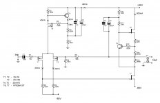
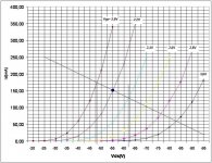
Dear Allen, could you check please the enclosed draft schematics aimed at SIT transistors implementation in power amp. Are there visible improvements? The enclosed curves were measured by me for some KP926A transistors.
Attachments
Hey Vladimir,
Have you plotted any curves for higher currents and lower voltages? And also for Ug=0V?
Have you plotted any curves for higher currents and lower voltages? And also for Ug=0V?
Member
Joined 2009
Paid Member
If you do try it with bipolars or darlingtons, then the positive temperature coefficient may be an issue. With mosfets, the transconductance is degenarative, but with bipolars the HFE is regenerative. Having both output transistors on the same heatsink will no doubt help but you may need to put a capacitor in series with R10 in the 3rd diagram.
The ltp current source is fairly temperature stable and the output drift is minimal with the mosfet output design. Alternatively use a 2nd aleph css on the output driver transistor as per the Aleph amps.
Thanks for the heads up, I'll have to look at this - don't want it blowing up 😱
Dear Allen, could you check please the enclosed draft schematics aimed at SIT transistors implementation in power amp. Are there visible improvements? The enclosed curves were measured by me for some KP926A transistors.
decouple between -80 and -85 is key factor
R4 = 0
connect R3 to -80
connect fine adjustable 20mA CCS from input mosfet drain to -85V ,so DC isn't flowing through R3
bias lower SIC with source resistor
Hey Vladimir,
Have you plotted any curves for higher currents and lower voltages? And also for Ug=0V?
These KP926A start to loose triodicity at higher currents, I did measurements at Vgs=0, at low Vds Id grows linearly, then bends down like for ordinary j-FET and finally Id close to constant. Therefore I suppose these SITs are good for transformer output only.
decouple between -80 and -85 is key factor
R4 = 0
connect R3 to -80
connect fine adjustable 20mA CCS from input mosfet drain to -85V ,so DC isn't flowing through R3
bias lower SIC with source resistor
Thanks a lot, quite instructive. Decoupling you mean independent power supplies? Source resistor to make necessary Vgs for lower SIT if we connect R3 to -80 ? Then we do not need -85 at all ?
Last edited:
.....Decoupling you mean independent power supplies? ....
I meant - that way as you drew it - every ripple between -80 and -85V is directly visible at gate of SIC
this way is better - drawn already as concept in Aleph J thread ( for cascoded LU instead plain IRFP
Attachments
I meant - that way as you drew it - every ripple between -80 and -85V is directly visible at gate of SIC
this way is better - drawn already as concept in Aleph J thread ( for cascoded LU instead plain IRFP
What current will flow through R3 in this case ?
What current will flow through R3 in this case ?
just AC signal - for SIC modulation ;
this way you can alter it in value , up or down , according to your needs
I have never played around with buried channel devices only standard jfets. The triode characteristic looks nice at those currents and it may make a good headphone amp.
- Status
- Not open for further replies.
- Home
- Amplifiers
- Pass Labs
- Aleph Current Source Mod