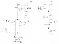
Here is an updated draft schematics. Internal resistance of SIT is nearly 60, NFB helps to decrease Rout, then output trafo decreases Rout additionally by factor 16. Peak current to load will be 4A, correct?
Attachments
Last edited:
seems that 4A is correct figure
anyway - if you wish easier setting procedure of exact circuit - be sure to make at least one CCS adjustable
anyway - if you wish easier setting procedure of exact circuit - be sure to make at least one CCS adjustable
I am not sure I really like the need for the output transformer to lower the output resistance. I have no experience of SIT's but if the gate is buried by ion implantation and has two 'sides' what effect does this have on the input capacitance in comparison with conventional fets? I have heard conflicting stories about SITS. Does anyone have a spice model?
Incidentally, earlier in the post we were talking about the ability of the feedback controlling transistor to effectively control an output transistor with low Vgs/Vb etc. My spice model for a BC639 gives a Vcesat of a few hundred mV. A device picked at random measured less than 10mV, ICC=5mA, IBB=0.5mA
Incidentally, earlier in the post we were talking about the ability of the feedback controlling transistor to effectively control an output transistor with low Vgs/Vb etc. My spice model for a BC639 gives a Vcesat of a few hundred mV. A device picked at random measured less than 10mV, ICC=5mA, IBB=0.5mA
I am not sure I really like the need for the output transformer to lower the output resistance. I have no experience of SIT's but if the gate is buried by ion implantation and has two 'sides' what effect does this have on the input capacitance in comparison with conventional fets? I have heard conflicting stories about SITS. Does anyone have a spice model?
Tride-like output characteristics of SITs mean relatively low internal device resistance (nearly 60ohms in my case, Ciss nearly 1500pF) compared to ordinary FETs. Of course SITs are more suitable for No NFB designs. But without NFB the only way of getting close to reasonable Rout is using output transformer. In the schematics shown above the NFB is very small (consider 500kohms resistor in the NFB). A reason why I think about SITs is something related to their interesting sound, that I found with SIT based preamp.
Vladimir - which types of Russian SIT-s are worth chasing
Google is little picky with Russian pages , so I can't use it with much results
Google is little picky with Russian pages , so I can't use it with much results
Vladimir - which types of Russian SIT-s are worth chasing
Google is little picky with Russian pages , so I can't use it with much results
Real SITs are KP801 (low voltage aimed at audio) and KP926 (high voltage, aimed at switching designs).
something new?..
In my case, the story has ended with the foolowing schematics
http://www.diyaudio.com/forums/pass-labs/220963-sit-amp-idea.html#post3254225
There are many opinions that common drain is not the best implementation of SITs, but practical listenings say that power SIT is perfect for this schematics.
After I have added el caps at the output (near 50000uF per channel), the low end became absolutely perfect, better than with RF power bjt at the output.
- Status
- Not open for further replies.
- Home
- Amplifiers
- Pass Labs
- Aleph Current Source Mod