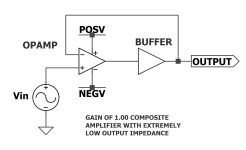
To get another factor of 1000X reduction in output impedance: use (your favorite buffer) as the second stage of a composite amplifier. In this composite amplifier, the first stage is an opamp with enormous open loop gain. As has been successfully demonstrated in M2x-Norwood, M2x-Milpitas, WHAMMY, etc. Thanks to the global negative feedback loop, the output impedance of the buffer is reduced by the gain of the opamp:
Obviously you still need to ensure the global loop is stable, since both the opamp and the buffer contribute added phase (reducing phase margin). But it can be done; it has been done; and working examples abound.
_
Zout_composite(s) = Zout_buffer(s) / Opamp_open_loop_gain(s)
Obviously you still need to ensure the global loop is stable, since both the opamp and the buffer contribute added phase (reducing phase margin). But it can be done; it has been done; and working examples abound.
_
Attachments
Indeed, feedback helps. In Aleph Bet, however, we explored a different approach, where the buffer is a simple follower, and feedback is used only to servo its operating point.
Speaking of M2x, here is one prototype of Aleph Bet in the form factor of M2x daughter card:

I don't have an M2x, yet, but the buffer already performs flawlessly.
Speaking of M2x, here is one prototype of Aleph Bet in the form factor of M2x daughter card:
I don't have an M2x, yet, but the buffer already performs flawlessly.
.. and I always thought a pnp has the base current going out.No, everything is as in the schematic. U1 provides the current which R8 and T3's base sink.
hi i do not want to derail from the topic but if you goal is to drive a 2kohm load with 2V and low THD there could be alternative As usual sims provide only an idea of possible performanceWith all the due respect, I’m also interested in this topic. ...
Attachments
hi thank you very much Too good to be true
I am using sim without having a sufficient understanding of what i am doing I saw that someone proposed the concept in an old thread and i got curious
better to go back to transistors Maybe in that case results are more dependable
i am fascinated by simple topologies
I am using sim without having a sufficient understanding of what i am doing I saw that someone proposed the concept in an old thread and i got curious
better to go back to transistors Maybe in that case results are more dependable
i am fascinated by simple topologies
Sorry but a LM317 is light years away from what I’m looking 😉 This topic attracted my attention because the design has a FET input (therefore very high input impedance et minuscule bias current), a very low distorsion and a low noise. That’s not something that is achieved by integrated circuit, as far as I know.hi i do not want to derail from the topic but if you goal is to drive a 2kohm load with 2V and low THD there could be alternative
So far, playing with my simulation version, which should be pretty accurate, I understood the great benefit of the output current compensation. I’m much less convinced by the benefit of cascoding the FET. In fact, I’m more or less convinced that it’s a bad idea for a buffer that has already a low input capacitance, except maybe to increase the input voltage range. A "degenerate cascode" could maybe offer the benefit of a large input voltage without the drawback of a weird input impedance. Well, this design makes me think 🤔
I made a big error in the previous post when I said that I was not convinced of the benefits of cascoding: it’s in fact mandatory because there is no way to have a decent distortion without cascoding.
Anyway, I continued to play with idea of a designing a very low distortion FET buffer. My current result is in the picture that follows. I don’t know if it’s covered by Nelson Pass patent or not, but the idea is the same.
Anyway, this design is not usable for at least 2 reasons: it’s too noisy and the input impedance is too weird. But, the THD is quite good thanks to resistors that are matched to 0.05% (which I admit is crazy). However, there is no need to match anything else. Well I thinks it’s a kind of an upper bound of what is possible with currently available JFET.
You should look at Samuel Groner's "A Low Noise Laboratory-Grade Measurement Preamplifier" published in Linear Audio, Volume 3, April 2012. There, he explains much of how low noise design works before presenting his actual circuit.
On a different note: maybe you should take your design effort to a separate thread instead of highjacking this one? Low noise amplifier design is a whole different subject from what I have been trying to promote here with Aleph Bet.
On a different note: maybe you should take your design effort to a separate thread instead of highjacking this one? Low noise amplifier design is a whole different subject from what I have been trying to promote here with Aleph Bet.
- Home
- Source & Line
- Analog Line Level
- Aleph Bet, a single stage, single ended ultra low distortion buffer
