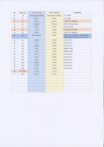
The xlr and rca has its own gnd connection on the pcb so there's no need to use a jumper. The zener Z1 - Z4 reading just won't stop after 5 minutes, it seems to be going up and up but can be measure by using AC value. I have also measured the bad channel's R41 resistor value, it is at 1.0 ohm. I suspect the fet is not accurately matched. I also suspect the capacitor C5 (No.43) is not doing its' job. The R7 (No.7) measurement seems to vary form 0.1mv between 0.6mv, so i put in the highest value. Please let me know your thoughts. Thanks.
pmchoong said:The R7 (No.7) measurement seems to vary form 0.1mv between 0.6mv, so i put in the highest value.
For the bad channel.
Hi again,
No problem at R7. Looking at your chart I'm assuming that you misplaced the decimal point on the reading for the good channel for R15. Aside from that, your readings all look acceptable to me.
Apparently your fets arent matched at all, but the amp should operate OK.
There should only be one ground on the board, if your input ground is isolated from it that is the entire problem. Getting back to your XLR wiring, #1 is the signal ground and must go to the board ground. The 4th terminal you were referring to is chassis ground and most people dont use it. Also, if you are using the RCA inputs you need to tie the XLR - [cold] to ground . That's what the jumper does that you are referring to, I think
Bill
Bill Fuss said:
Apparently your fets arent matched at all, but the amp should operate OK.
You meant the bad channel's R41's Q7 fet, correct?
Bill Fuss said:
There should only be one ground on the board, if your input ground is isolated from it that is the entire problem. Getting back to your XLR wiring, #1 is the signal ground and must go to the board ground. The 4th terminal you were referring to is chassis ground and most people dont use it. Also, if you are using the RCA inputs you need to tie the XLR - [cold] to ground . That's what the jumper does that you are referring to, I think
Sorry, I did not mention this : there is only 1 gnd on the board which runs on the edge of the board and the xlr and rca and other circuit gnd is connected to this gnd.
The input gnd you are referring to is the IEC gnd, correct?
You do not suspect the C5 readings have anything to do with this.
Attachments
The input ground is the #1 pin on the XLR and the ground lug on the RCA. They should go to the board ground.
Actually, the voltage across C5 is another way of measuring the offset voltage on the output. They match quite well.
Now you have to apply a signal to the inputs and with your meter set on AC you must follow the signal through the amp, taking readings just as you did with the DC readings. You should be able to find the problem area. This time start at the input with no speakers.
Bill
I forgot one thing, now all the readings are from the circuit to ground so hook one probe to a convenient grounding point.
Another thing I forgot to have you check is the ground path resistance. Measure from the RCA ground to the neg. speaker terminal, it should be close to zero.
Bill
Another thing I forgot to have you check is the ground path resistance. Measure from the RCA ground to the neg. speaker terminal, it should be close to zero.
Bill
Bill Fuss said:Another thing I forgot to have you check is the ground path resistance. Measure from the RCA ground to the neg. speaker terminal, it should be close to zero.
RCA ground to neg. speaker terminal = 0
Bill Fuss said:The input ground is the #1 pin on the XLR and the ground lug on the RCA. They should go to the board ground.
Yes, they are connected to the board.
Bill Fuss said:I forgot one thing, now all the readings are from the circuit to ground so hook one probe to a convenient grounding point.
Hi Bill
You mean :
1) plug in an input, eg. CD player and start playing
2) hook one probe to a grounding point, eg. star ground
3) measure other parts on the pcb with the other probe
4) turn DMM knob to AC
Correct?
Good timing, I just got up.
Yes, set it on a low scale and check the signal going to and coming out of Q1. If you look at the schematic the signal goes straight to the output fets gate resistors from there. That is the basic signal path.
Yes, set it on a low scale and check the signal going to and coming out of Q1. If you look at the schematic the signal goes straight to the output fets gate resistors from there. That is the basic signal path.
Bill Fuss said:Looking at your chart I'm assuming that you misplaced the decimal point on the reading for the good channel for R15.
You are absolutely correct. My mistake.
I did the AC measurement on the bad channel. Most of the components can't be measured. Please see attachment. I put the negative probe onto the star ground and took measurement with the positive probe on each componet when the CD is playing. Thanks.
Attachments
OK, I know what you mean now. You wont get steady readings unless you have a signal generator or a test CD.
On Q4 do you get anything from collecter to ground, it should be a higher range of voltages than what you saw at the rca.
On Q4 do you get anything from collecter to ground, it should be a higher range of voltages than what you saw at the rca.
I rechecked the measurement at R2,3,4,5 and 8 = between 0.003-0.010, the measurement jumps. But at R13 = 0.003v
- Status
- Not open for further replies.
- Home
- Amplifiers
- Pass Labs
- Aleph 5 problem 2