Well, the IRFP244s that I so carefully matched into groups of six have now been mounted onto the output PCBs.
Time to see how close my matching was at something like the operating current that they will be used at:-
Board No.1 0.7% Not Bad
Board No.2 0.5% Even Better
Board No.3 2.0% Worse but still very good
Board No.4 was just about to be tested when the doorbell rang.
The percentage figures are the "match" between Vgs as measured across Rs on each MOS-FET. They were tested at Igs 2.4A/6 = 400mA and Vcc = 24V. In the final circuit they will be at Vcc = 48V but the same current.
I can't seem to find any advice as to whether it is better to have the better matches in the current source or the amplifying device position.
On completeion I'm going to have LOTs of IRFP244s left over, most of which are matched into close pairs.
The actual matching figures after working them out on the computer were
Bank 1 0.53%
Bank 2 0.66%
Bank 3 2.03%
Bank 4 1.05%
All well within target.
Now the question; Which bank to use in which position.
Bank 1 0.53%
Bank 2 0.66%
Bank 3 2.03%
Bank 4 1.05%
All well within target.
Now the question; Which bank to use in which position.
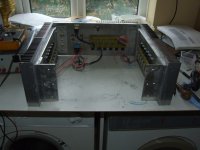
I'm now in the process of putting the whole beast together.
I did have a worry that the bank of MOS-FETs on the rear panel would not be adequately sinked.
Interesting.
FET No6 on the right hand side of the bank gets quite hot, even though it is on 10mm Ally plate which is shared.
Obviously the single heatsink on the rear cannot dissipate the heat of the F4 but I would expect the heatsink on the left hand side to get hot.
Why is the heat not being shared around the enormous ally chassis ?
Everything has been polished and coated with a "smear" of heat transfer compound.
I did have a worry that the bank of MOS-FETs on the rear panel would not be adequately sinked.
An externally hosted image should be here but it was not working when we last tested it.
Interesting.
FET No6 on the right hand side of the bank gets quite hot, even though it is on 10mm Ally plate which is shared.
Obviously the single heatsink on the rear cannot dissipate the heat of the F4 but I would expect the heatsink on the left hand side to get hot.
Why is the heat not being shared around the enormous ally chassis ?
Everything has been polished and coated with a "smear" of heat transfer compound.
By the way. Just to test my E-Bay IRFP244s I set the bias to 25A and they coped beautifully. Even if they are fakes they are working in this situation.
Wouldn't recommend leaving the bias there though as things were getting WARM.
Wouldn't recommend leaving the bias there though as things were getting WARM.
Finally I gave into "Mr Fan". The PABT 24V 120cm fan running at 10-12V is almost silent. With the fan running and the rear bank biassed at 25V and 9A (250W) the MOS-FET side of the hestsink is at a comfortable 45 degrees and the outside almost cool to the touch.
Last edited:
I would like to try and get the fan inside the case though, not because it's noisy but because it spoils the sleek lines of the design.
My intention is to fit a pair of heatsinks on the inside of the case and cool them with fans. a) this will reduce noise further, b) they will be cooling the MOS-FET side of the chassis and c) it will look better.
My intention is to fit a pair of heatsinks on the inside of the case and cool them with fans. a) this will reduce noise further, b) they will be cooling the MOS-FET side of the chassis and c) it will look better.
It's getting a bit busy in here:
It's also starting to get a bit HEAVY
It's also starting to get a bit HEAVY
Attachments
Last edited:
I would like to try and get the fan inside the case though, not because it's noisy but because it spoils the sleek lines of the design.
My intention is to fit a pair of heatsinks on the inside of the case and cool them with fans. a) this will reduce noise further, b) they will be cooling the MOS-FET side of the chassis and c) it will look better.
this will not reduce noise. you will get at least 6-12db more noise because of the forced airflow inside the chassis.
All 24 MOS-FETs now fitted and undergoing LOAD TESTING to ensure that HEATSINKS are adequate.
I hate the fan on the rear but I can't seem to find a better way of getting rid of the heat from the fouth side. You cant see it anyway and the 24V fan running at 9V is virtually silent.
I was very impressed with the MOS-FET matching, all four bankc are within less than 1%.

I hate the fan on the rear but I can't seem to find a better way of getting rid of the heat from the fouth side. You cant see it anyway and the 24V fan running at 9V is virtually silent.
I was very impressed with the MOS-FET matching, all four bankc are within less than 1%.
I'm knackered. Cutting 10mm Alluminium Plate by hand is hard work.
Still in the true DIY spirit, I am not going to cheat by spending hard earned money when it isnt necessary.
This is the bottom plate being manufactured, it needs to be so thick in order to support the enormous weight of the build so far plus the two massive toroids.
Still in the true DIY spirit, I am not going to cheat by spending hard earned money when it isnt necessary.
This is the bottom plate being manufactured, it needs to be so thick in order to support the enormous weight of the build so far plus the two massive toroids.
Attachments
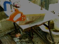
I did try a JigSaw but my JigSaw just couldn't keep hold of the blade and it kept falling out.
I suppose I could have used a nail file.
I suppose I could have used a nail file.
Now for the Power Supplies.
I am using 12 x 33000uF Dubilier Computer Grade Capacitors. They actually measure at nearer 90000uF each.
There are four banks of three caps, one each for LEFT +ve LEFT -ve, RIGHT +ve and RIGHT -ve. 100000uF in each bank (or 300000uF as measured).
I bought 4 x 22mH Air Cored Chokes and 4 x 0R47 25W Resistors.
Question is, What combination of CRCLC will give the best results.
Within the limits of PSU2 that I could use, it would appear that CLCC is the best option.
Unfortunately the simulation just says that the diodes will blow, not surprising when I can only specify 1N5400s. I'm using 50A bridges.
Unfortunately the simulation just says that the diodes will blow, not surprising when I can only specify 1N5400s. I'm using 50A bridges.
How can you put a 50A bridge into PSU2 ? As far as I could use it it would only allow 1N5400 diodes that fused under the huge capacitors that I am using,.
Utter rubbish. the 50A bridges surive perfectly with CCC loading.
Utter rubbish. the 50A bridges surive perfectly with CCC loading.
33000uf caps that measure nearly 300% their rating consistently? are you sure your meter just cant measure such a huge value properly?
Quote>I'm knackered. Cutting 10mm Alluminium Plate by hand is hard work.
For straight cuts Forghet the hand saw and the Jig saw much faster and accurate with an angle grinder and metal cutting disk.
You could get the 1 mm thick ones and the 4 1/2 in grinder can be bought for £20 £30.
Just let the disk do the work keeping light passes against a straight edge there is a knak to it less force and more patience is the secret.
I built the Vauxall plant with it (well my share of it)
On the caps what do you use to mesure them my meter gives up at 10mU
Attachments

- Status
- Not open for further replies.
- Home
- Amplifiers
- Pass Labs
- Aleph 4 Strickly DIY Project Build