Hi,
I have finished yesterday my Mini A using BrianGT pcbs.
I haven't installed R10 and shorted C1. The thing is I do not understand the gain anymore.
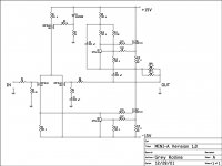
In the seminal GRollins schematics the gain was 1+R8/R6 (GRollins schematics)
If I kept R10 and C1 (BrianGT schem) I would calculate the gain as 1+R15/R10. Is that correct? If so if I follow the gain formula with R10=infinity I get gain equal to 1?
Now (without R10 and shorted C1) the gain is controlled by R15. How to calculate it.
The background of my question is that while I find my Mini loud enough I expected more power. In fact it is quieter than my ACA.
I run my Mini with +/-15.8V and 1.3A. The speakers are about 95dB.
I have finished yesterday my Mini A using BrianGT pcbs.
I haven't installed R10 and shorted C1. The thing is I do not understand the gain anymore.
In the seminal GRollins schematics the gain was 1+R8/R6 (GRollins schematics)
If I kept R10 and C1 (BrianGT schem) I would calculate the gain as 1+R15/R10. Is that correct? If so if I follow the gain formula with R10=infinity I get gain equal to 1?
Now (without R10 and shorted C1) the gain is controlled by R15. How to calculate it.
The background of my question is that while I find my Mini loud enough I expected more power. In fact it is quieter than my ACA.
I run my Mini with +/-15.8V and 1.3A. The speakers are about 95dB.
I hoped Zen Mod would chime in!
Here are the diagrams I was referring to.
Did I mention that I am running my amp in the unbalanced mode.
Do I need to ground -IN then ?(then I could sort of see the analogy with GRollins schematics and the gain would be 1+R15/R9=11 using BrianGT part numbers)
Many thanks!
Here are the diagrams I was referring to.
Did I mention that I am running my amp in the unbalanced mode.
Do I need to ground -IN then ?(then I could sort of see the analogy with GRollins schematics and the gain would be 1+R15/R9=11 using BrianGT part numbers)
Many thanks!
Attachments
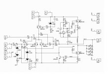
short C1 , remove R10 , ground -IN
remove R3 , increase R2 to 1M
then calculate gain with helpp of any operational amplifier cook book , using example of non-inverting amplifier
I would do that for you , but my brain is in sushi form , while still consuming first morning coffee 😉
besides , what's difference between 10 vs. 11 V/V
all that ref. to BrianGT sch
chime in again if your output offset is above , say , 75mV in temp equilibrium
Got it. Will try in the evening (have to work for my boss now to pay for those goodies).
Was I correct then that with the floating -IN my gain was 1 (OK less than 1 because of the divider formed by R1 and R2||R3)?
Was I correct then that with the floating -IN my gain was 1 (OK less than 1 because of the divider formed by R1 and R2||R3)?
Hi,
So I shorted -IN to GND. I think this gives me way too much gain (and I can hear some hum - but that's probably due to too small capacitors tank 30000uF for both channels each pos and neg leg). So I decided to lower the gain adding 10K to R9. So I effectively have R9=20k, R10=infinity and R15=100k. So my gain would be 1+100/20. Any ill effects of this?
Why do you suggest replacing R2 and R3 - increasing input impedance. I already have a B1 in front of the Mini A. what would change technically and soundwise is I do that?
BTW What a great little amp!
The offset seems to be under 10mV.
For the first time in my life my heatsinks are big enough. The top is just slightly above lukewarm the bottom is coldish.
For the first time in my life my heatsinks are big enough. The top is just slightly above lukewarm the bottom is coldish.
in original (say that , for temporary clarity sake , those two Minis are originals) , gain is established with values of 100K and 10K
everything messing up with those two values (connected to important nodes) is .... just mess-up
properly high values of additional resistors are doing their job (keeping gate at gnd potential ) while not influencing feedback net values and operation
everything messing up with those two values (connected to important nodes) is .... just mess-up
properly high values of additional resistors are doing their job (keeping gate at gnd potential ) while not influencing feedback net values and operation
R6 is the so called McMillan resistor. R6 can be used to minimize DC output offset. Apparently it has a lot of influence (negative) on the sound of the amplifier. Ideally you leave out R6. Proper matching of the input differential pair ensures low DC output. If you have to use R6, start with 47k.
Search for McMillan resistor, lots of info in the Aleph X thread.
Search for McMillan resistor, lots of info in the Aleph X thread.
aha , ref. to sch. in post #183 ;
as Rodeodave sez - that's the patch
better without reason for it , so no need for patch
as Rodeodave sez - that's the patch
better without reason for it , so no need for patch
- Status
- Not open for further replies.
- Home
- Amplifiers
- Pass Labs
- Aleph 30 the best choice of C1 C2 C3 on brian gt PCB