reference to sch in first post of this very thread.
R10 is , say, bleeder for (un-needed) input cap
R10 is , say, bleeder for (un-needed) input cap
reference to sch in first post of this very thread.
Doh! same schematic......
Thanks!
reference to sch in first post of this very thread.
R10 is , say, bleeder for (un-needed) input cap
Hi!Zen ,thanks for your reply....a little question for your answare:
Are you sure that your considerations about c1 and r1 are correct also for the balance use of the amp?
If yes.. for you, why Mr.Pass had used this items ?
Thanks in advance.
Zen Mod;2965917 - foolproof reasons[/QUOTE said:but from you advice, that is, remove C1 and R10, would not seem so foolproof 😀, why precisely, Mr. Pass, designed the circuit with these two components,,, is not it?😕
because of possibility that his amp is going to buy some ignorant bstrd , eager to connect it to source with some DC on output ?
😉
😉
because of possibility that his amp is going to buy some ignorant bstrd , eager to connect it to source with some DC on output ?
😉
perfect, now it is all clear, except for a small doubt that inquiries concerning R10, that is, if you Elima this resistance, you do not create an imbalance between the two half-waves of negative and positive, the audio signal?
I say this because I see that on the input signal positive there the resistor network formed by R1/R2/R3 and negative input is formed by the resistive network R9/R10.
thanks for your patience.😉
do not worry
as I said - look Babelfish J sch
as I said - look Babelfish J sch
An externally hosted image should be here but it was not working when we last tested it.
is it save to use 25V cap for Aleph30 power supply? I was going to purchase in PCX for nichicon super through 15.000uF 50V, but when I look at MUNDORF M-Lytic AG @25V with cheaper price, it's a huge improvement on cap bank capasitance size. need your advice.
- Nichicon ST -> 8 x 15.000uF 50V @$27 = $216 (total 120.000uF)
- Mundorf Ag -> 12 x 47.000uF 25V @$17 = $204 (total 564.000uF)
I find that papa is using 25V caps on his F5
- Nichicon ST -> 8 x 15.000uF 50V @$27 = $216 (total 120.000uF)
- Mundorf Ag -> 12 x 47.000uF 25V @$17 = $204 (total 564.000uF)
I find that papa is using 25V caps on his F5
Last edited:
.......
I find that papa is using 25V caps on his F5
........
enough said .
xformer secondaries - 2x18Vac
enough said .
xformer secondaries - 2x18Vac
perfecto, 2 pcs of 2x18Vac 225VA, 4x47.000uF 25V per channel.
while 6x47.000uF 25V per channel seems too big capacitance
Asking, asking, asking always lead to a better result 🙂 Since Talema only have maximum rating on 18V @225VA, is it big enough for 1 channel? or should I get bigger one such as Antek 2x18V 400VA?
just use what's easier to buy/pay/ship
it's anyway hard to sim properly if you don't have exact Rdc values of both primary and secondary
R in CRC will take care of excessive current suck from rectifier and xformer
anyway, be sure that 4x47mF will be already perfect for one channel
it's anyway hard to sim properly if you don't have exact Rdc values of both primary and secondary
R in CRC will take care of excessive current suck from rectifier and xformer
anyway, be sure that 4x47mF will be already perfect for one channel
enough said .
xformer secondaries - 2x18Vac
2 x 18VAC?????😱
I do not remember where or who, but I'm sure you informed on the need to have 2 x 22VAC to power aleph 30 and, in the case of common power supply for both channels, the filter formed by CRC 4 x 22.000uF / 2 x 1 ohm 10W / 4 x 22.000uF
oh boy ........
well - I'm sure that I made my homework ........
all roads lead to Rome
if you want 25V caps , 2x18Vac will give you roughly 2x22Vdc
if you use higher voltage caps , be my guest and use up to 25Vac xformer
1R in CRC is a hell , if you ask me
well - I'm sure that I made my homework ........
all roads lead to Rome
if you want 25V caps , 2x18Vac will give you roughly 2x22Vdc
if you use higher voltage caps , be my guest and use up to 25Vac xformer
1R in CRC is a hell , if you ask me
Always look at schematic before doing changes 🙂 I don't even find any R on Aleph30 original design of "Pass Aleph 30 Owner's Manual", it's only 6x10mF without mentioning voltage rating. I think that CRC design came up on FirstWatt line series
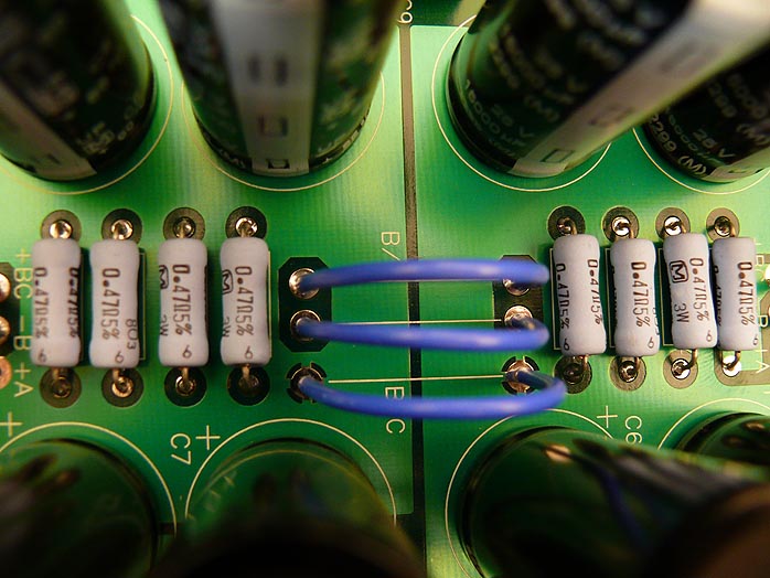
I think that R should be 0R1, using 3 parallel 0R3 5W is my choice
I think that R should be 0R1, using 3 parallel 0R3 5W is my choice
oh boy ........
well - I'm sure that I made my homework ........
all roads lead to Rome
if you want 25V caps , 2x18Vac will give you roughly 2x22Vdc
if you use higher voltage caps , be my guest and use up to 25Vac xformer
1R in CRC is a hell , if you ask me
Sorry,i have too a 22-0-22 Vac trafo with crc psu filter
2x22000uF (40vdc) 0.33ohm 2x22000uF (40vdc) for one only Rail
on the output of psu i have about 27Vdc for each rail.
Please is ok this working voltage?
If no please can you give me some advice about it?
I think I should enhance the resistor of the crc
can you confirm the value and the power of this resistor?
I think 1 ohm 10w should be ok.
I also think the ripple should be ok with these values of CRC.
Thanks in advance.
Last edited:
Sorry,i have too a 22-0-22 Vac trafo with crc psu filter
2x22000uF (40vdc) 0.33ohm 2x22000uF (40vdc) for one only Rail
on the output of psu i have about 27Vdc for each rail.
Please is ok this working voltage?
just go for it
decrease that R to 0R15 or 0R1
just go for it
decrease that R to 0R15 or 0R1
Sorry but decrease means increase the output voltage!😱
Are you sure?

- Status
- Not open for further replies.
- Home
- Amplifiers
- Pass Labs
- Aleph 30 the best choice of C1 C2 C3 on brian gt PCB