Hi all
I believe that someone before me have this kind of problem but the search option didn't come up with result.
I manage to burn one chanell of Aleph30 ;-)
So does any one have some idea what could cose that I have half of power supply voltage on speakers output ?
When I measure voltage on source resistors ( 0.5/5W) on side with Q9/Q11/Q13 I have 0.45V but on the other side I have around 0.1V across source resistors resistors.
What should I check ?
Thanks
(p.s. I'm not an expert, this is my hoby and I only have one multimeter ;-))
I've got two meters, and managed to let out plenty of the magic smoke. Looking at the A30 service manual, I don't see any Q13. Which schematic are you using? Maybe a close up pic if possible.
-john
-john
first check output mosfets for shorts
desolder suspicious ones and retest , when you find malfunctioning half (lower or upper)
desolder suspicious ones and retest , when you find malfunctioning half (lower or upper)
MEGA-amp said:I've got two meters, and managed to let out plenty of the magic smoke. Looking at the A30 service manual, I don't see any Q13. Which schematic are you using? Maybe a close up pic if possible.
-john
sorry for misunderstanding.
I was reading from PCB markings so I state Q13 and so. The PCB that I'm using is from BrianGT GB and there was shematic with it but I have reinstall windows and didn't have time to transfer old files on new one, so at this moment I don't have original shematic for those PCB.
A friend diyer have send me original Alwph30 service manual and the mosfets that I'm talking about are Q6-Q8
Could someone please send me shematic that have come with Brians Mini and Aleph 30 PCB since there is difference in markings betwin original and Brians.
And it's hard for me to track diferences by looking on PCB
(email josip.katalinic at gmail.com)
Thanks
Zen Mod said:first check output mosfets for shorts
desolder suspicious ones and retest , when you find malfunctioning half (lower or upper)
Is it posibile to check output mosfets while thay are solder ?
couse I have chack them and they all mesure the sime...
it seams that Brian's schematic is close to the original;
I have masure voltage over
- R11 - 5V - o.k.
- Q3 Dpin to 0 - 4V o.k
- Q5 - 4.5V - I think o.k.
- R14 - I have 3.1V not o.k.
and I have notice something strange at least visualy...bacause I don't think that I solder this bad ;-) but the PCB under Capacitor ( I think it's C11 ) looks burned ?
not shure is C1 on this pcb the C11 on original shematic ?
http://www.diyaudio.com/forums/showthread.php?postid=585816#post585816
Attachments
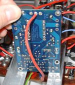
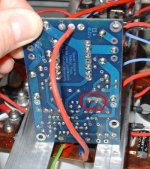
Here it is again with red cloud ;-)
one more thing...
this amp was working fine, for some time, until I conect wrong output of 7.1 preamp (NAD S170) to onother amp which couse one Alpeh 30 amp to make some duuulllll/tuuull sound and after couple sec it start to smell bad ;-)
I don't know how conecting wrong preamp output to other amp can make some amp which is conected to another output to burn ? but !
...complicated story...it would be much easyer to draw it then to describe it with words...
(sorry for bad english)
Attachments
OK - seems that you have problems with biasing of output , not with burned output mosfets
check zenners for short , especially one in input CCS ( 9V1)
I'll send you Algar_emi's A30 pdf , with all measuring points , so you can compare ... and write here what's difference
check zenners for short , especially one in input CCS ( 9V1)
I'll send you Algar_emi's A30 pdf , with all measuring points , so you can compare ... and write here what's difference
Zen Mod said:OK - seems that you have problems with biasing of output , not with burned output mosfets
check zenners for short , especially one in input CCS ( 9V1)
I'll send you Algar_emi's A30 pdf , with all measuring points , so you can compare ... and write here what's difference
I have recive pdf ... thanks Choky ;-)
will play a litlle and post results...
For now...
Colegue diyer advised me to mesure voltage on ZTX base.
I have conect one side of multimeter to the ground and with the other I mesure voltage on Q4 base which is like 21V and on the Q5 is like 13V.
( I mesured resistance betwin ZTX leegs , they are not shorted so I think thay are not broken )
Colegue diyer advised me to mesure voltage on ZTX base.
I have conect one side of multimeter to the ground and with the other I mesure voltage on Q4 base which is like 21V and on the Q5 is like 13V.
( I mesured resistance betwin ZTX leegs , they are not shorted so I think thay are not broken )
Measure Vbe (voltage between base and emitter) of ZTXs, not the base voltage per se, although it won't hurt.
O.K.
top view ( o represents pins )
Q5 o 4.62V o
3.9V o 0.64V
Q4 o 5V o
4V o 0.6V
not shure but this should be like when woching from component side
c e
b
whell it looks diferent when I post, so if I'm right bouth have around 0.6V betwin b and e, and 5 or 4.6 be twin c and e.
top view ( o represents pins )
Q5 o 4.62V o
3.9V o 0.64V
Q4 o 5V o
4V o 0.6V
not shure but this should be like when woching from component side
c e
b
whell it looks diferent when I post, so if I'm right bouth have around 0.6V betwin b and e, and 5 or 4.6 be twin c and e.
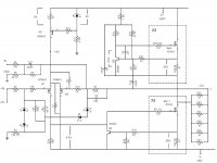
yoke , it's useless ( at least to me ) to post without known nomenclature ;
use this schematic , and just disregard part names on pcb ;
I know ( and have in my PC ) too much Aleph schematics , to even remotely be sure what you're talking about , without exact schematic ...
I hope it will help
use this schematic , and just disregard part names on pcb ;
I know ( and have in my PC ) too much Aleph schematics , to even remotely be sure what you're talking about , without exact schematic ...
I hope it will help
Attachments
Zen Mod said:yoke , it's useless ( at least to me ) to post without known nomenclature ;
use this schematic , and just disregard part names on pcb ;
I know ( and have in my PC ) too much Aleph schematics , to even remotely be sure what you're talking about , without exact schematic ...
I hope it will help
you are rigth
there are several schematic of Aleph30 with diferent markings...
and it's been a while since I build this ;-)
lets resume
power is +/-22V
I have around 13V on the output
R11 - 5V
R14 - 2,5V
Z5 - 9V
Q5 - from c to e 4.6V from b to e 0.6V
Q4 - from c to e 5V from b to e 0.6V
Q 6-8 source resistors 0.5V
Q 9-11 source resistors 1V
something is wrong
you can't have in same time 2V5 across R14 , and 5V across c-e of Q4
what value of source resistors you have , and how many output pairs ?
you can't have in same time 2V5 across R14 , and 5V across c-e of Q4
what value of source resistors you have , and how many output pairs ?
you are right - I have problems indetifaing resistors but voiltage is 5V on ztx
I have 2 x 3mosfets (just like original) and source resistors are 0.5Ohm
I have 2 x 3mosfets (just like original) and source resistors are 0.5Ohm
in my xperience ( lifetime as repair techie ....... lousy one  ) - fastest and most convenient way of repair - for simple circs as A30 is - is simply to pull out ( ONE BY ONE , to ensure possible mixing ) all semis
desolder it , pull out , measure
if good - solder it back , if suspicious - replace , if broken - replace
check input LTP ( both IRF9610) , for start ;
what WAS initial current through outputs - when you made amps ?
to me - seems that even 0V5 across each source resistor is on highish side ...... not to mention 1V ..........
) - fastest and most convenient way of repair - for simple circs as A30 is - is simply to pull out ( ONE BY ONE , to ensure possible mixing ) all semis desolder it , pull out , measure
if good - solder it back , if suspicious - replace , if broken - replace
check input LTP ( both IRF9610) , for start ;
what WAS initial current through outputs - when you made amps ?
to me - seems that even 0V5 across each source resistor is on highish side ...... not to mention 1V ..........
Yes it seams that would do the trick...resolder everything...
The thing is that I can't keep amp on for a more than a fiew sec since the side with 1V on source resistors start to smell ;-)
so I have to turn it on and off...
About voltage on source resistors, 0.5V is normal....I think it drops to 0.45 once the amp heat's up. I think that this 0.25V on original shematic is wrong. It should be like 0.5V.
1V is to much and I have to find out what is cosing it.
will try to mesure some voltage over input pair of mosfets.
- Status
- Not open for further replies.
- Home
- Amplifiers
- Pass Labs
- Aleph 30 problem - half of power supply voltage on speakers output