
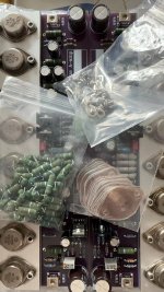
Today I put one of my Aleph 2s on the bench for some measurements. I have not made any changes yet, and the amps had not been switched on for a while. It was a hot day today (35C) so a perfect day to work in a steel shed with a hot class A amplifier haha. Well, actually, we waited until 6pm before switching it on. By then the temperature in the shed had dropped to about 25C.
Prior to this, we cut a 400m length from a length of 40x25x1.6mm angle aluminium and drilled eleven 30mm holes in it. As this was just a prototype, we superglued eleven 30mm 24V fans to the bottom of the aluminium. Mounting them with a drop of super glue meant not all the 30mm openings were completely covered by the fan (difficult to get them exactly in the right spot) so we knew the resulting airflow could be improved upon by better position and possibly using silicone or something else to seal them properly.
We put the feet of the Aleph 2 on some wooden slats to increase the space under the heatsink in order to be able to put the angle aluminium with the fans under one side of the amp.
Next we switched the Aleph 2 on and let it cook for half an hour. This was without the fans mounted under the heatsink so we would have some idea what it was like in its unmodified state. My new gadget, a Uni-T UTi120s thermal imaging camera, came in really handy to keep an eye on the heat. Yes, the heatsinks got hot. After about half an hour we were at 65C, not quite as hot as the simple laser pointing infrared gun had showed, but still hot.
We then placed the 400mm angle aluminium under the heatsink (with the fans blowing air up), with the 25mm side of the angle aluminium covering the bottom 25mm of the heatsink to aid the air flow up (sorry, forgot to take photos). Powering the fans with a bench psu at 24V showed an immediate temperature decrease but, although the individual fans could hardly be heard at that speed, having 11 blowing air through the fins was noticable. It would be fine with some music, but I knew it would annoy me on soft parts in classical concerts, so we dialed the voltage down and found that at 17V the noise was quite low (sitting 2 feet from the amp). We kept the amp on for a while until the temperature of the heatsinks had settled. We measured a drop of about 13C!
We then took the lid off to measure the temperature of the mosfets. These were 72-75C on the side without the fans, and 61-64C on the side with the fans. Assuming both banks of 6 mosfets produce about the same heat, the fans kept the mosfets about 11C cooler. Not a bad result from a suboptimal prototype!
The next step will be to make 3 more of these fan holders, mount the fans properly and stop any air leaks. I just hope I have enough fans. I bought 50 on Aliexpress, but had to discard 2 out of the 13 tested: 1 was dead and the other was noisy.
To be continued.
I knew my Aleph 2 was running at too high voltage (230V primary 2 x 40V secondary transformer), so while it was on the bench it was a good moment to check what the voltage actually was.
At the last 47000uF capacitors in the CLC setup we measured -56.4V and 56.4V, so quite a bit higher than the 45V rails specified in the Aleph 2 service manual!
We also measured the AC ripple at the first and second C in the CLC setup. While it was just over 100mV at the first, the 2.2mH inductor had reduced this to just under 5mV, which I though was quite an achievement.
I will really have to look at reducing the voltage of the rails. Buying new transformers is an expensive option to replace the perfectly good Talema 1kW transformers currently installed, so I think I will try the RCLC approach I mentioned earlier first (adding 0R75 before the first C). It will also be interesting to see what the remaining ripple will be.
Using a clamp meter we measured about 2A on the negative supply and a little bit higher (2.2A) on the positive supply rather than the 3A I expected. I think I read somewhere that the amp varies the bias current depending on the rail voltage, so possibly that is what I was seeing.
I have not started yet on the new front end circuit boards (thanks @rhthatcher) and will continue mucking around with the psu and fans in the current configuration before introducing new variables.
Also to be continued.
56v rails, you’re well on your way to 60V Aleph 1.2 territory. Good thing you’re running fans. With the new front end board you’ll be able to easily adjust the bias current. Be careful with heat and mosfet dissipation with those rail voltages. The A1.2 uses 2x the MOSFETs and bigger heatsinks. So cranking to 3A will likely yield a little rail voltage sag, and it will also test the limits of the MOSFETs and heatsinks - even with the fans.
Did you solve your A2 problem?
I have quite the opposite problem, I am trying to operate at a lower voltage. My thought now is +-38V after deliberated for months, considering lower cost for lower voltage capacitors, transformers of manageable size, but nothing is final until the transformers are bought, so far only two 40V capacitors bought last week are the only things that refrain me from going for higher voltage.
I am building two pairs of A5 clones to use with active crossover. well, sort of A5 for I do not know how to call it since I intend to run it with approx. +-38V (28V transformer output), 4 volts higher than A5 but 7 volts lower than A2, probably get around 70W with it. Intend to drive my speakers with low impedance of 6 ohm norm. and 1.5 ohm min.
Bought the kits from China, but also bought extra MOSFETs with it, so there are a total of 72 matched IRF250 between them, and another 16 matched IRF250 (4 sets of 4, but not matched to the 72) for the original set of A5.
Thought I will use 36 MOSFET in each pair, I.E. (9+9) MOSFET in each channel. The 16 MOSFET that are not matched to the 72 will be left out for now.
The vendor is still trying to look for another 24 matched MOSFET, if I am lucky then the amps will have 24 MOSFET per channel, same as Aleph 1.2 but with only 1/3 of the power of 1.2.
Q1) When use with 1200VA transformer per channel, would that be sufficient to cope with low impedance speakers?
Q2) Am I too conservative to restrict it to only 70W? I would like the amplifiers to be able to cope with 1 ohm at its lower, but not 0.5 ohm. What optimal power output when use with 9+9 MOSFET to drive speakers with 1 ohm impedance? And corresponding transformer secondary voltage?
Q4) what optimal power output when use with 12+12 MOSFET to drive speakers with 1 ohm impedance? And corresponding transformer secondary voltage?
Thank you and have a great week ahead!
Attachments
Last edited:
Just check MOUSER and their ex-stock for more than 100 capacitors of 40V, 100,000uF that sat there for the last 2 months are suddenly gone! Someone must have grabbed the lot! New stock only arrive in 33 weeks! Not week 33 but 33 weeks later!
Good news is that I will get some freshly baked stock from the oven, Bad news is I will have to wait till April 2025!
Good news is that I will get some freshly baked stock from the oven, Bad news is I will have to wait till April 2025!
I know a guy with enough IRFP240's for multiple Aleph 1.2's.... Send me a PM.
Have you played with the old Aleph calculator spreadsheet to play with voltages, current, power output, etc? See this link:
https://www.diyaudio.com/community/...ating-tool-like-axe-1-but-for-aleph-2.146039/
Have you played with the old Aleph calculator spreadsheet to play with voltages, current, power output, etc? See this link:
https://www.diyaudio.com/community/...ating-tool-like-axe-1-but-for-aleph-2.146039/

He is swimming in them the last I heard.I know a guy with enough IRFP240's for multiple Aleph 1.2's.... Send me a PM.
Have you played with the old Aleph calculator spreadsheet to play with voltages, current, power output, etc? See this link:
https://www.diyaudio.com/community/...ating-tool-like-axe-1-but-for-aleph-2.146039/
fabulous!I know a guy with enough IRFP240's for multiple Aleph 1.2's.... Send me a PM.
Have you played with the old Aleph calculator spreadsheet to play with voltages, current, power output, etc? See this link:
https://www.diyaudio.com/community/...ating-tool-like-axe-1-but-for-aleph-2.146039/
Thanks for the spreadsheet! I didn’t know it exist, I was guesstimating from the voltage rails and power output of Aleph 1.2, 2 and 5.
That it will pump out 8 times its rated output at 8 ohm when it is presented with 1 ohm load and stable at that.What is your expectation for this amplifier at a one ohm load?
Having a pair of Martin Logan Quest now that go low but not as low as the scintilla.
I live in an apartment and I only listen to my music at moderate sound level. But I would like the amplifier to deliver what it should at that particular moment when the load dip.
So I think power of between 50~100Wrms/ch@8 ohm should suffice, but it should also do 400~800Wfms/ch@1 ohm load.
It sounds like you have experience in that area, please feel free to advise.
Thank you.
This is really useful!I know a guy with enough IRFP240's for multiple Aleph 1.2's.... Send me a PM.
Have you played with the old Aleph calculator spreadsheet to play with voltages, current, power output, etc? See this link:
https://www.diyaudio.com/community/...ating-tool-like-axe-1-but-for-aleph-2.146039/
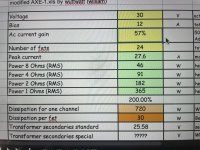
I added a row for the 1 ohm load, using the same formula in the spreadsheet.
So by varying the Bias current and/or AC current gain I could achieve the desired output at 1 ohm (that doubles when load is half).
Questions:
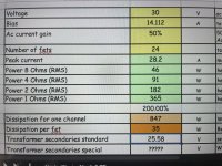
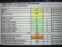
1) what is the effect of bias current on sound quality (10A vs. 14A as in picture 1)? and/or others, I noticed that the dissipation per fet shot up when I have a higher bias current, trying to recall my school days 35 years ago, does it move the quiescent point, which should be adjusted so that the signal output wouldn’t clip.
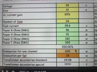
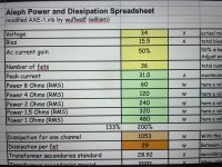
2) what is the effect of AC current gain on sound quality (50% vs. 65% as in picture 2)? and/or others. If higher percentage of current is by the current source, does it make the current source MOSFET hotter? should it be 50/50?
Pardon my ignorance, you may call me a non practicing electronic engineer.
Thanks.
Attachments
And if I have allowed (by varying bias current and AC current gain) for full output at 1 ohm, and sufficient no. FETS to ensure that it doesn’t overheat, do I still need to allow for extra VA capacity in the transformer wattage? The rows that read for factor 2, 3, 4…
You still want the VA rating to be significantly higher than your DC dissipation ( hence the 2x, 3x, 4x rows 🙂 )
This thread on the AC current gain may be of interest to you. https://www.diyaudio.com/community/threads/proper-current-source-adjustment.38033/
This thread on the AC current gain may be of interest to you. https://www.diyaudio.com/community/threads/proper-current-source-adjustment.38033/
🤣 well, I didn’t know where to start and 10A was there on the spreadsheet…, but I was going to use a 2500VA transformer for each channel, based on the fact that if I wanted to have around 75W@8 ohm and 600W@1 ohm, and allowing for the low efficiency of single ended class A…. And enormous heatsinks were planned for. And this excel table is really useful to help me to optimise the voltage rail (hence power) based on various restrictions.
In any case, in order to be able to drive 1 ohm load, either the bias current or AC current gain will have to be increased to meet that requirements. My previous guesstimate of +-38V voltage and 75W @ 8 ohm will have to be reduced to +-30V and 46W@8 ohm.
QUESTION: would +-30V voltage rail hamper the dynamic performance of the amplifier? Would it still produce the same audio quality as the Aleph 2, despite having as many MOSFET as the Aleph 1.2
I may have to reduce the rail voltage (if it does not affect the audio quality) lower based on my normal listening sound level. Would it?
What is not in the plan is the air conditioning to cool the room during summer. The heatsink and transformer will be shared by the Aleph and a class AB MOSFET amp based on the Accuphase M6000 that will be used during summer.
You bet! Absolutely, but summer air conditioning wasn’t planned for, but a class AB amp based on the Accuphase M6000 for summer co-sharing the heatsink and PSU is already in the plan 😉I assume NE WAY is aware he won't need winter heating with this amp. 🙂
Thank you very much Dennis for the link.You still want the VA rating to be significantly higher than your DC dissipation ( hence the 2x, 3x, 4x rows 🙂 )
This thread on the AC current gain may be of interest to you. https://www.diyaudio.com/community/threads/proper-current-source-adjustment.38033/
After playing around with it and comparing different voltages with different number of MOSFET and bias current, I got to 2 sets of numbers for the 2 pairs of Aleph 5 clones that I am building:I know a guy with enough IRFP240's for multiple Aleph 1.2's.... Send me a PM.
Have you played with the old Aleph calculator spreadsheet to play with voltages, current, power output, etc? See this link:
https://www.diyaudio.com/community/...ating-tool-like-axe-1-but-for-aleph-2.146039/
1) 8 MOSFET per channel (pic.1)
*VCC = 17V
*Bias = 7.1A
12W@8 ohm
24W@4 ohm
48W@2 ohm
96W@1 ohm
It appears that in order to keep the dissipation per FET to 30W and below, and to have output voltage constant regardless of the impedance, I will have to half the Aleph 5 VCC voltage.
2) 36 MOSFET per channel (pic.2)
*VCC = 34V
*Bias = 15.5A
60W@8 ohm
120W@4 ohm
240W@2 ohm
480W@1 ohm
Some of you may suggest that I could reduce my bias current, but in order to drive speakers effortlessly that may have as low as 1 ohm impedance, I will have to have 36 MOSFET per channel in order to keep dissipation below 30W/MOSFET.
Please feel free to point out mistakes in my calculations, if any.
Despite having different number of MOSFET, VCC and wattage, would the 2 amplifiers sound identical when playing music and having music output at 10Vrms?
I have been holding back ordering my transformer due to not knowing how the amplifier would perform at different VCC at different load, it looks like I will be able to order my transformer pretty soon!
Thank you!
P/S: part of the constrains that I have is that I have 16 matched MOSFET and 72 matched MOSFET, but the MOSFET from the batch of 16 and 72 aren’t matched and cannot be used together.
So my options are:
Amp 1; Amp 2
1) 8 MOSFET; 36 MOSFET
2) 12 MOSFET; 24 MOSFET
Attachments
- Home
- Amplifiers
- Pass Labs
- Aleph 2: plans to modify a 17 year old diy build