If you are planning on building this preamp, please read the Errata list on Post 777. Also, read at least Post 1 of the GB Thread.
I had been complaining to Hugh Dean (AKSA) a few weeks ago about the dearth of simple, but nice sounding preamps with muscle to swing 40 volts peak-peak. Why would we need a preamp to have so much muscle? There are quite a few unity gain current amps out there in want of a high quality preamp that can swing their outputs beyond the usual voltage limitations of a +/-15v rail supply. The Pass F4 is one that comes to mind. For the person who likes the sound of opamps (and nothing wrong with that), I recently discovered (a well-known fact by many, invented in the eaarly 1970's) that you can bootstrap an opamp with a pair of TO92 BJT's and 4 resistors to get it to work from +/-44v rails for 70v p-p swing. That was an eye opener for me, but alas, the sound of an opamp to me, just isn't enthralling. After all, my time to listen to music is limited, and when I do have time, it's SE Class A or nuthin' 🙂
So, Hugh was kind enough to make up a new preamp for me to address this need for a 40v swing SE Class A amp with guts and a nice SE Class A signature, but this time, SE Class A and very low THD. Hugh says the design is inspired by a Lender balanced input stage, but with a few tweaks added by Hugh. It is simple: just 4 BJT's and a CCS, or 5 actives if you count the BSP129 depletion mode MOSFET I employed for the CCS. Although simple, the predicted performance is quite phenomenal. Hugh provided me the basic schematic in LTSpice with a generic 12mA CCS. I had some BSP129's on hand so decided to use them. A DN2540 would also work as well and not require SMT soldering. I could not find readily LTSPice usable models for the BSP129, although a very comprehensive manufacture model is available - I asked for help over in the Software Tools Forum, and Keantoken was kind enough to take the factory model and port it to a easy to use model and symbol for me to plug into Hugh's circuit. So I owe a huge thanks to Hugh for the design, and Keantoken for the BSP129 model porting.
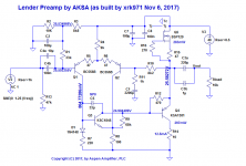
Here is the schematic of Hugh's Lender Preamp. As you can see, it is quite simple and I was able to veroboard prototype it quickly:

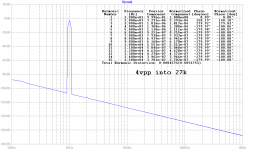
Before we go into the implementation, here are some predictions of the performance. I am assuming that the power amplifier input impedance is 27kohm, although 10k still looks very good. First at an output of 4v peak-peak and this is representative of typical very high volume levels one would ever need in a line-level preamp connected to a power amplifier with circa 20dB to 30dB gain. The distortion is exceedingly low in the ppm's and the nice thing is that it doesn't rise with frequency:
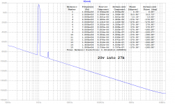
Here is the predicted FFT for 20v peak-peak output, a serious level and if driving a buffer power amp, only gets you about 6w rms with 8ohm speaakers, meh... but look at the low distortion figures (0.005%THD, the figures in parenthesis is the one I am using and think it includes THD+N?) and the nice descending higher orders from dominant 2nd order:

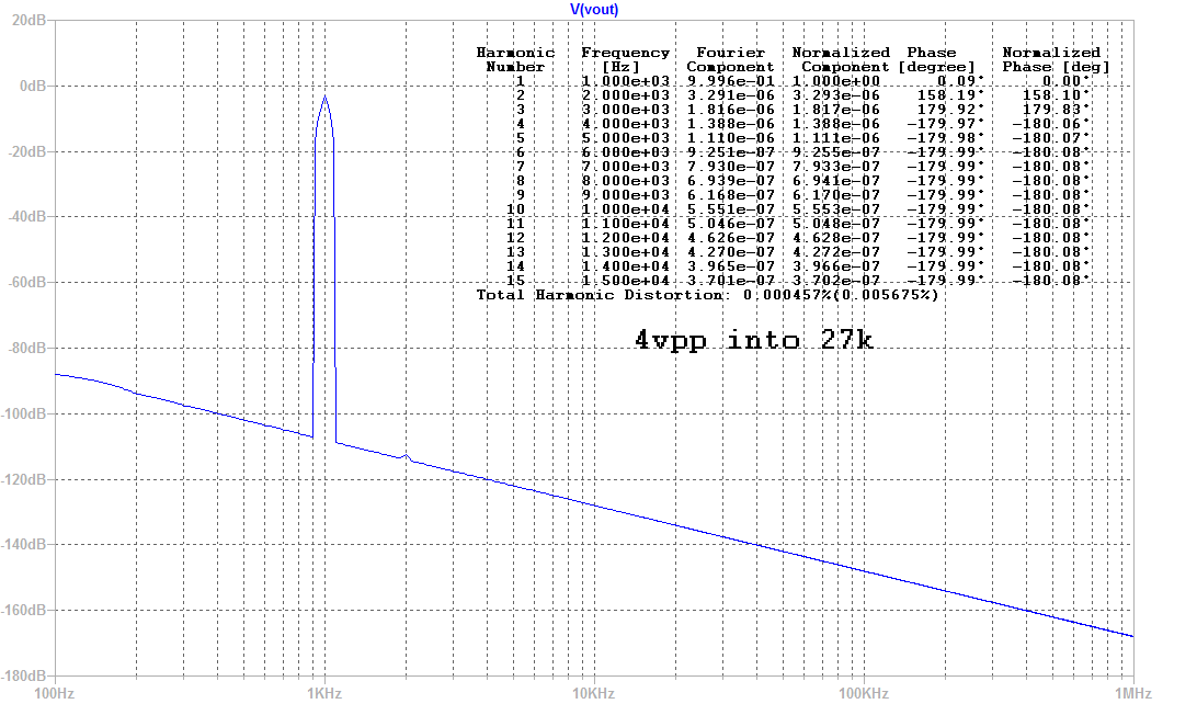
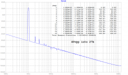
So, what if you need to drive 25w rms into 8ohms? Well, you need to swing 40v peak-peak. The predicted THD is still quite low and the harmonic profile is still beautiful with no higher orders going nuts. So this preamp can do it all: works well with normal high gain amps, and with unity gain current buffer amps like MOSFET followers:

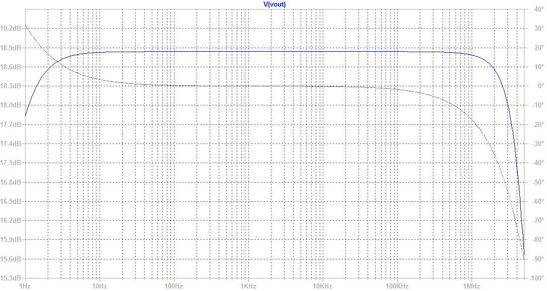
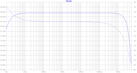
For completeness, here is the predicted frequency response and phase. Nice and flat from 10Hz to 1MHz. Phase is very flat too.
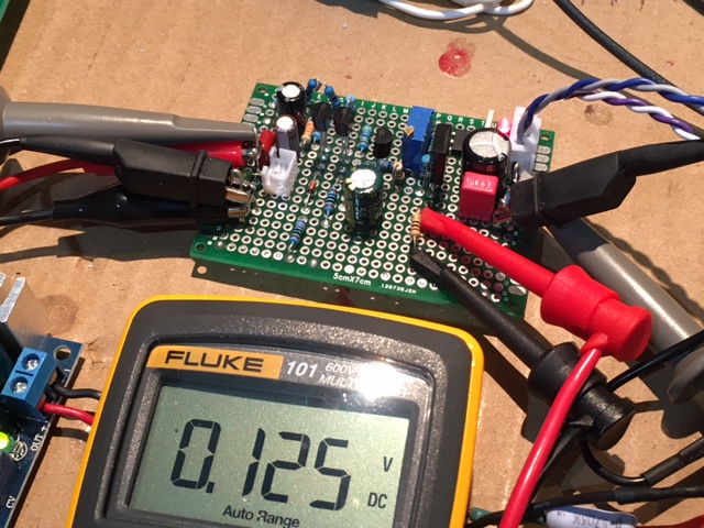
Here is my quick veroboard proof of concept build. I am using a simple DC-DC step up converter followed by a CRCRC to get 44.5v PSU rail that is pretty clean, shown is the 12.5mA (125mV over 10ohms) bias setting that I was adjusting using the pot (R15) on the BSP129:
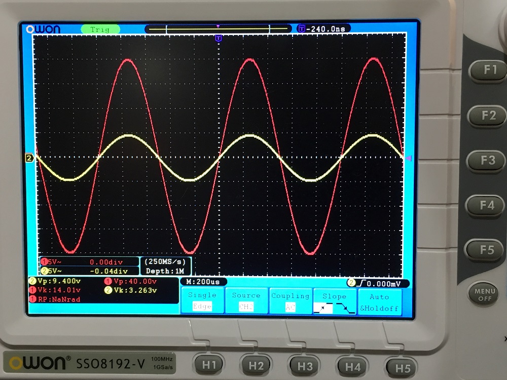
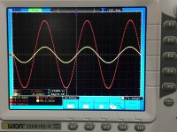
Here is the obligatory scope shot to show that indeed to makes 40v p-p. This was with an initial gain of 4.3x, which I later boosted to about 9.2x for later with still excellent results:
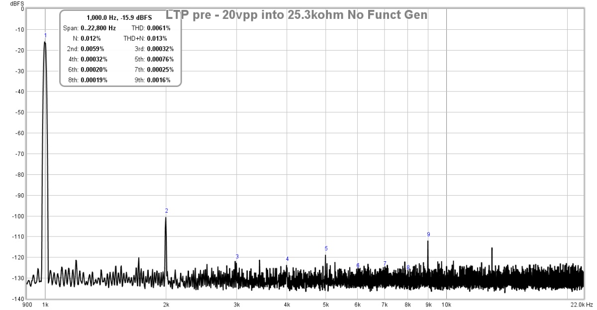
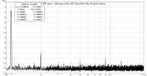
Here is the measured FFT for 1kHz input and 20v p-p output into a 25.3kohm load (27k plus a 10:1 voltage divider comprised of a 22k & 2k2 resistors):
Here is the measured FFT for 5kHz input and 20v p-p output into same load. As you can see, there is no rise in the THD:
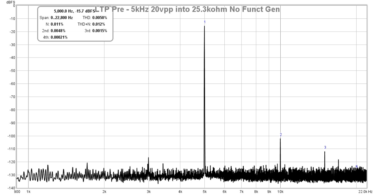
The FFT signal looks low because I was using a 10:1 voltage divider to drop the signal to a safe level for the Focusrite 2i4 2nd gen audio interface.
So how does it sound? Well, I only had one channel, so I connected it to both left and right inputs a low-distortion, DC-coupled, current feedback topology(read, neutral in character), commercial headphone amp (Schiit Magni 3) and listened with some DT880-250's and also Status OB-1's. The preamp sounds amazing. Very transparent, no hint of noise, hiss, or hum. Dynamics were outstanding, and in part, the transparency of te M3 allows the nature of the preamp to come through. Cannot comment on soundstage etc as only in pseudo stereo. But I expect that it will not disappoint based on phase margin predictions and THD and noise floor.
Edit Nov 12, 2017: I found a software glitch that caused the 5th and 9th harmonic. New measurements here:
http://www.diyaudio.com/forums/soli...lender-preamp-40vpp-output-4.html#post5242220
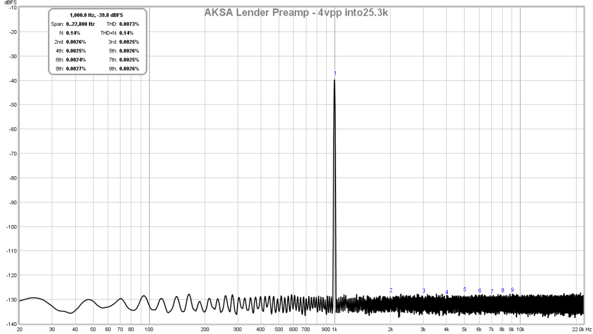
4vpp into 25.3kohm:
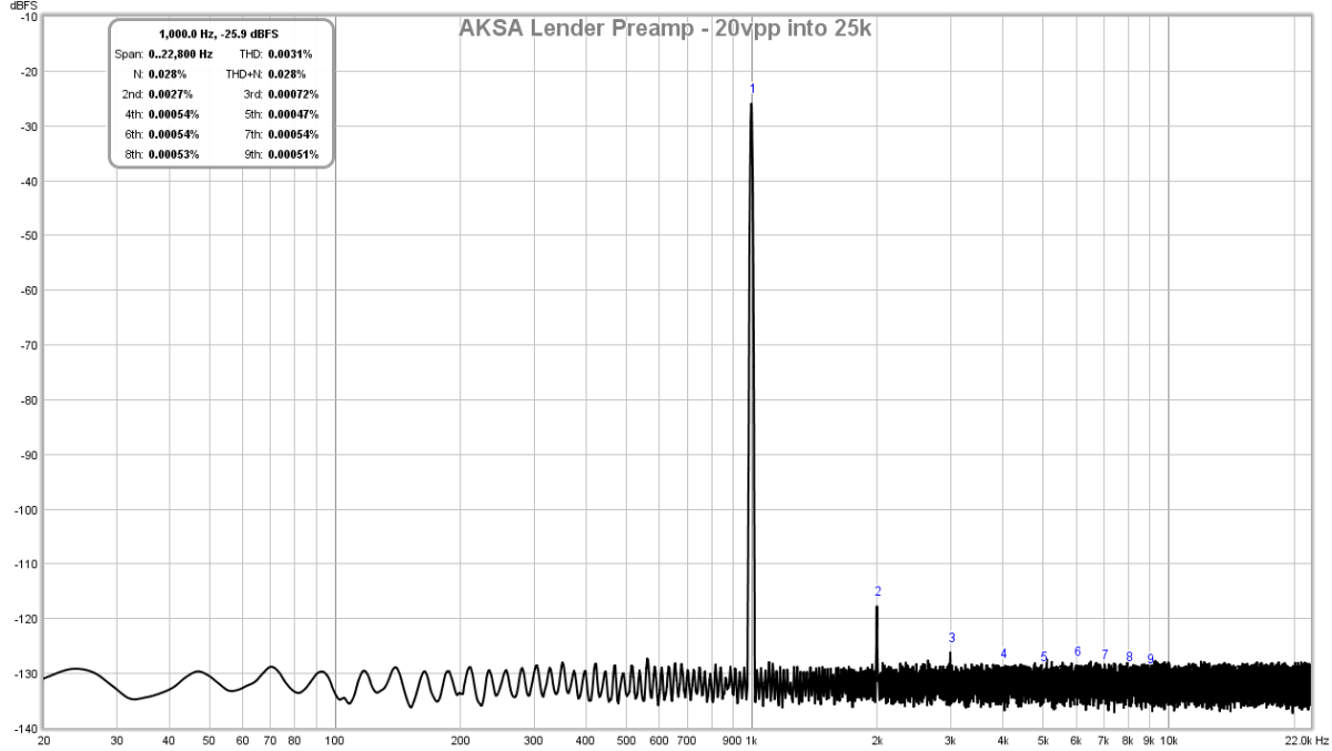
20vpp into 25.3kohm:
30vpp into 25.3kohm:
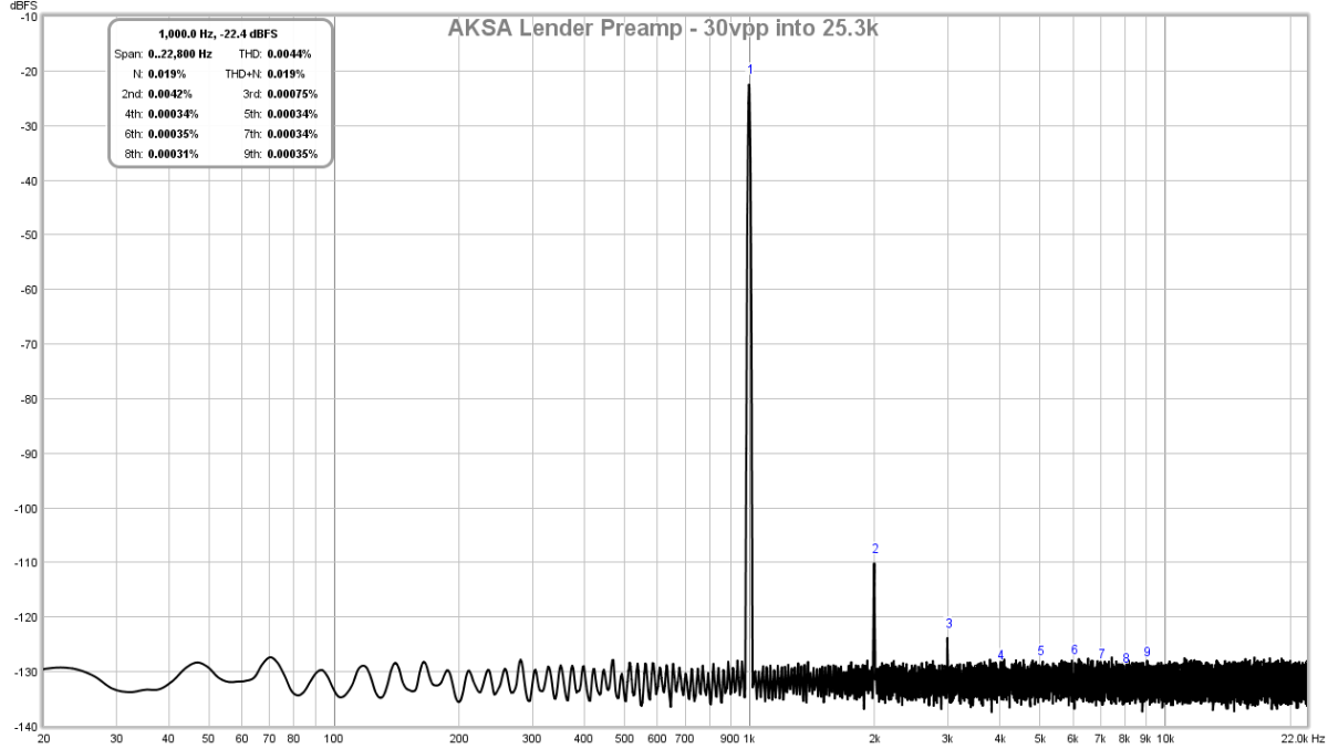
I think the measurements speak for themselves, this is a superb measuring and sounding preamp.
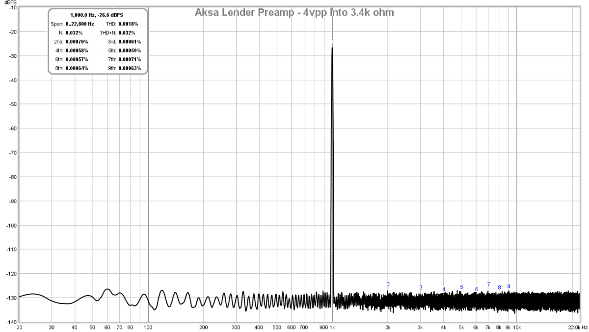
Edit Nov 13, 2017: Looking at performance into a lower 3.4k ohm impedance load.
http://www.diyaudio.com/forums/soli...lender-preamp-40vpp-output-5.html#post5242398
Here is FFT for 4v p-p into 3.4kohm load:
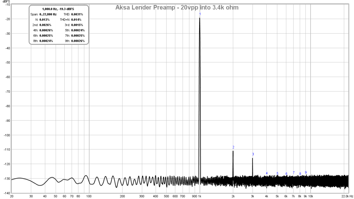
Here is FFT for 20v p-p into 3.4kohm load, still very admirable performance:
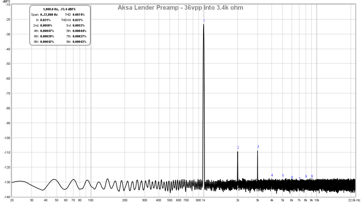
Here is FFT for 36v p-p into 3.4kohm load, here the H2 and H3 are about the same and any higher in amplitude results in clip:
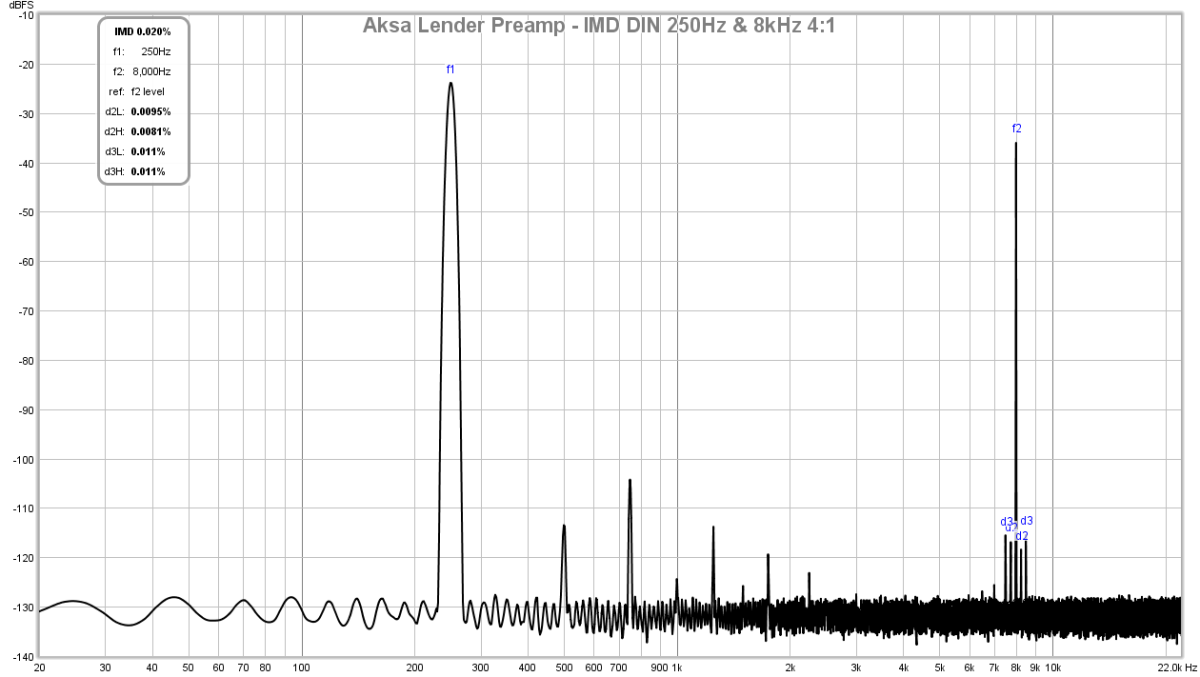
Here is IMD (DIN standard 250Hz and 8kHz 4:1) for 20vpp into 3.4kohm yields 0.02% IMD:
Here is IMD ((DIN standard 250Hz and 8kHz 4:1) for 20vpp into 25kohm yields 0.01% IMD:
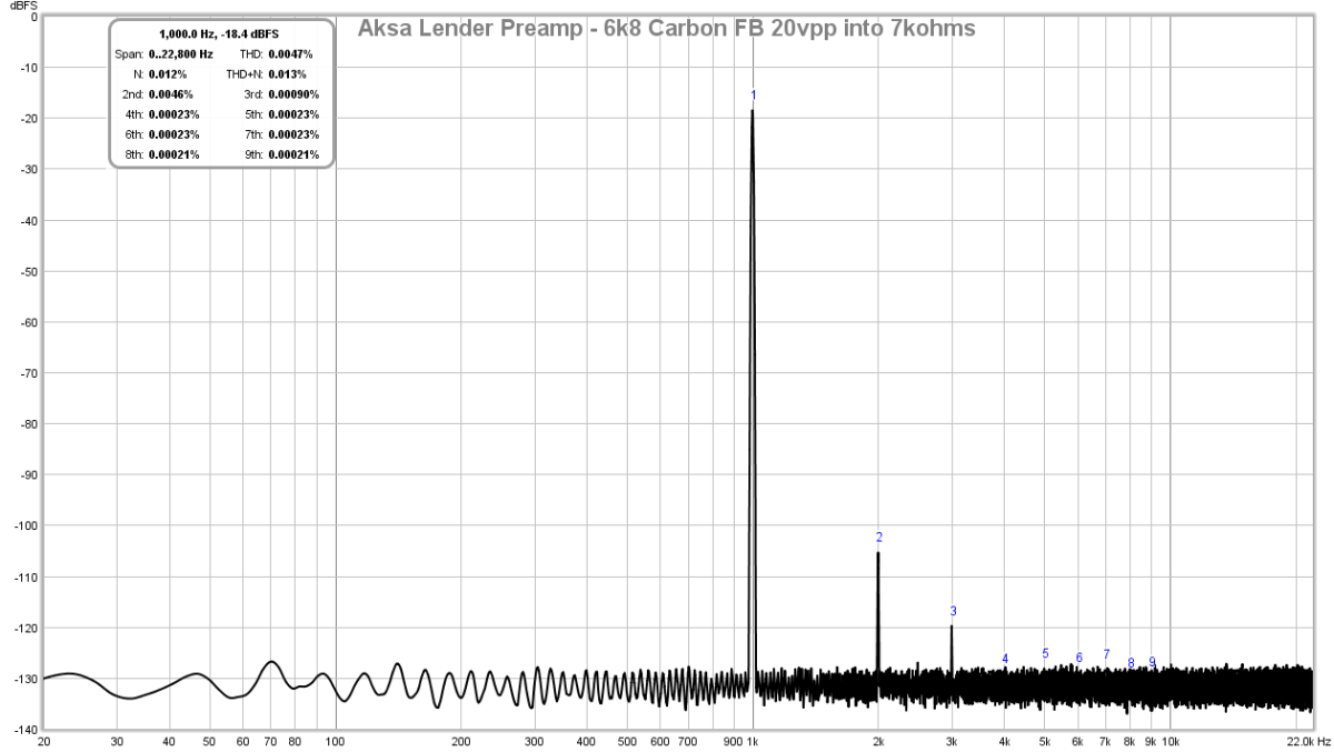
Edit Nov 17, 2017: Here is the final design laid out in SMT with exception of 1 resistor (R10) is a carbon composition and you can find out why here. The feedback resistor is 6k8 and the LTP emitter degeneration resistors are 47R. I am now getting -85dB for H2 and -100dB for H3, and nothing else. It is a superb sounding profile - engaging, great dynamics, full of energy yet natural sounding. Here is 20vpp driving 7kohms. Noise floor is deep deep black with no hint of any mains peaks.
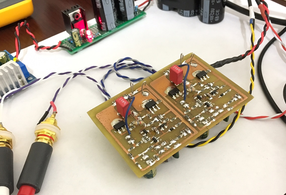
Preamp looks like this:
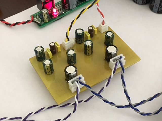
Other side:
I love how it sounds. Sublime.
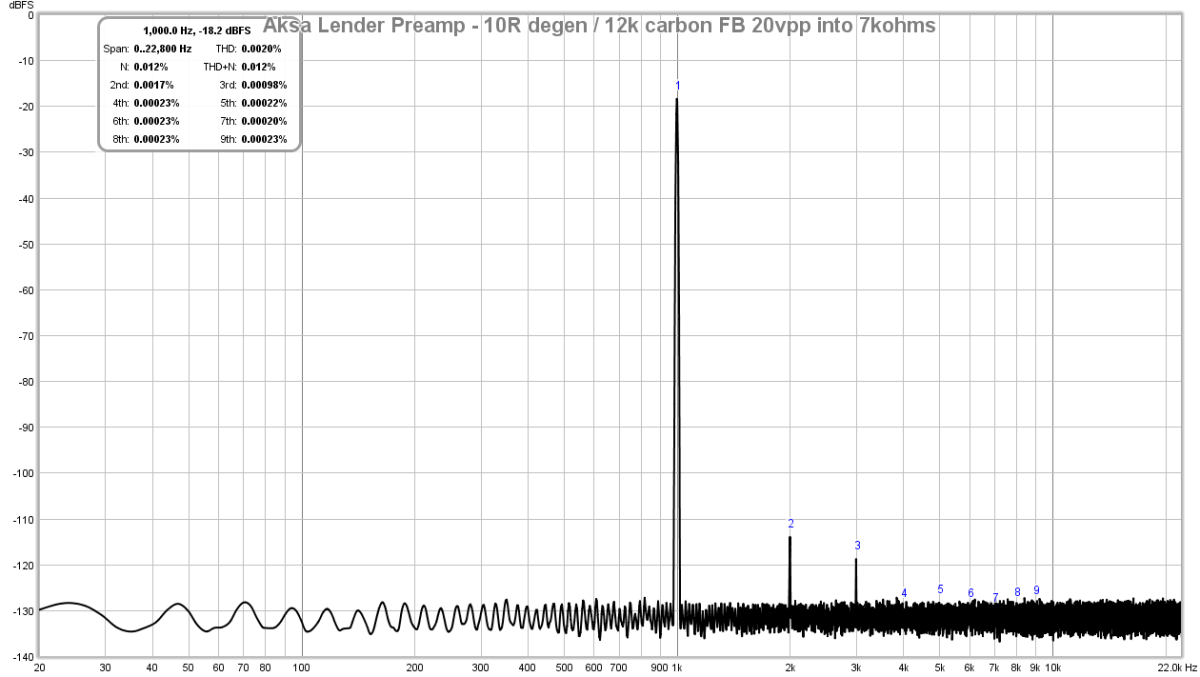
Edit Nov 17, 2017 - Bimo requested boosting gain to about 12x and show distortion profile and THD. With 10R degeneration resistors on LTP and 12k carbon resistor on R10, we get this for 20vpp into 7kohms - 0.002%THD and nice profile with only H2 and H3:
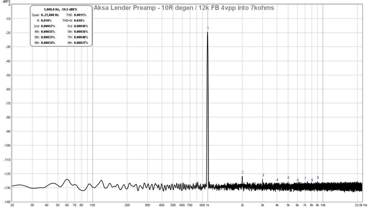
For line level driving of typical amps that have some gain, no more than 4vpp will ever be needed and here the FFT and THD for 4vpp into 7kohms we get 0.0011% THD and H2 is only5.7ppm:
Edit Nov 18, 2017 - perhaps the title should be modified to 70vpp? Here is a recent simulation with 100v Vcc showing a nice result for 70vpp output into 10kohm load with a 20dB gain setting on the amp. THD is predicted to be 0.0077% with a nice profile.
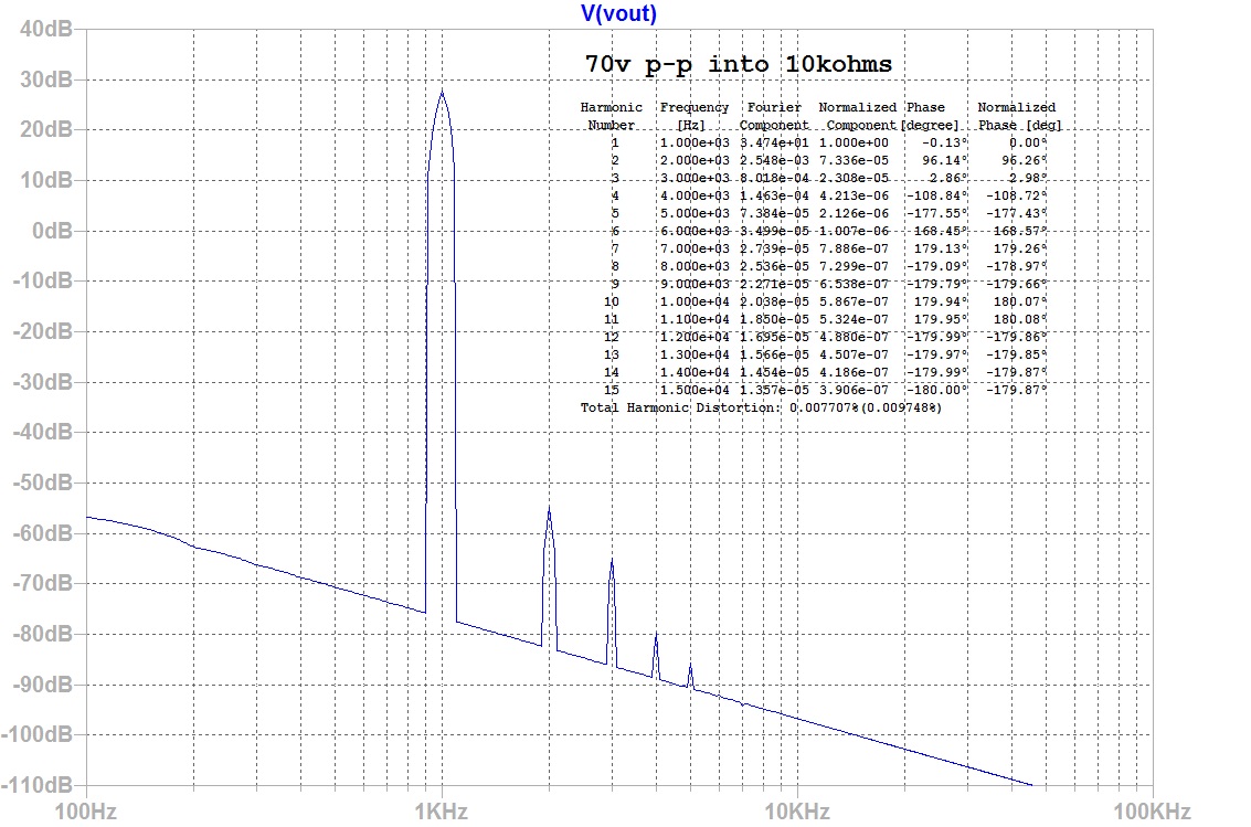
To do this requires changing the input LTP devices to MMBT5401 (or 2N5401 for through hole builds) and adjust R4b to 17k to keep 2.5mA current in the LTP. Change the degen resistors R5/R6 to 3.3ohms, and R9 to 100k. Make sure all electrolytics are revised to handle max voltages of 100v on rail and output node and 63v elsewhere.
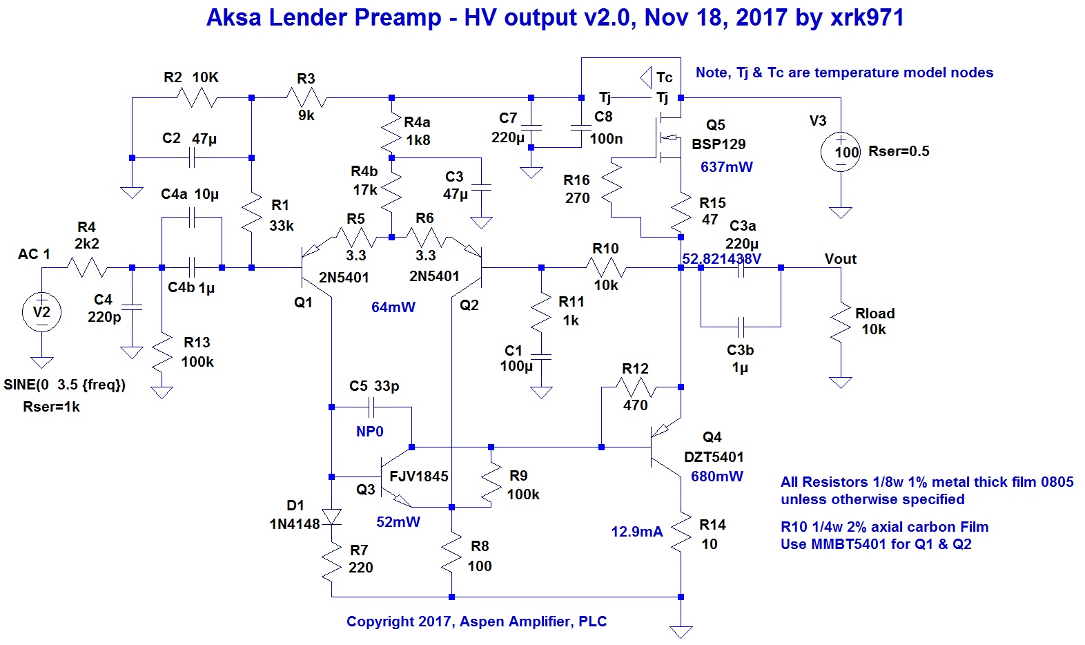
Here is schematic v2.0 for the HV amp:
Group Buy here:
http://www.diyaudio.com/forums/group-buys/315521-aksas-lender-preamp-40vpp-ouput-gb.html#post5261067
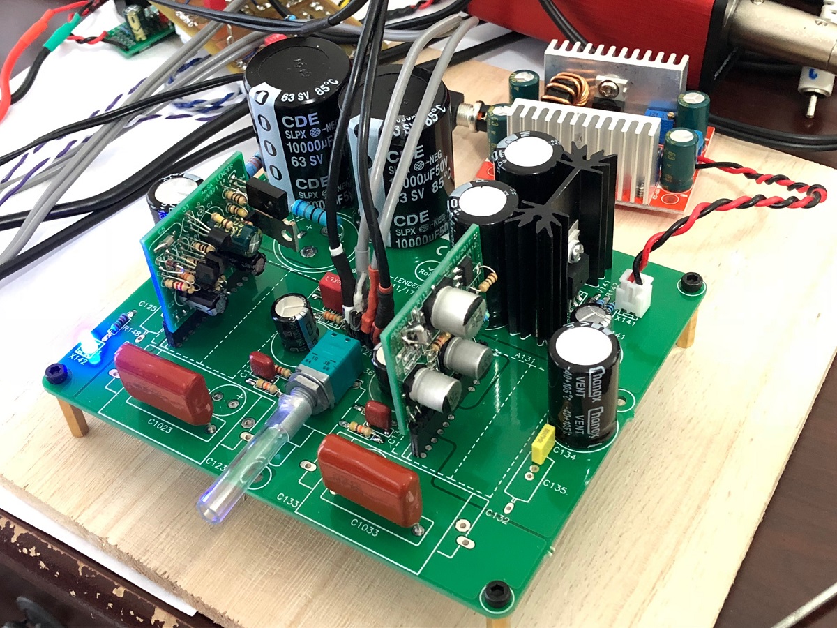
Edit Dec 10, 2017: GB boards verified to be working. Here is MB with TH and SMT daugterboards installed.
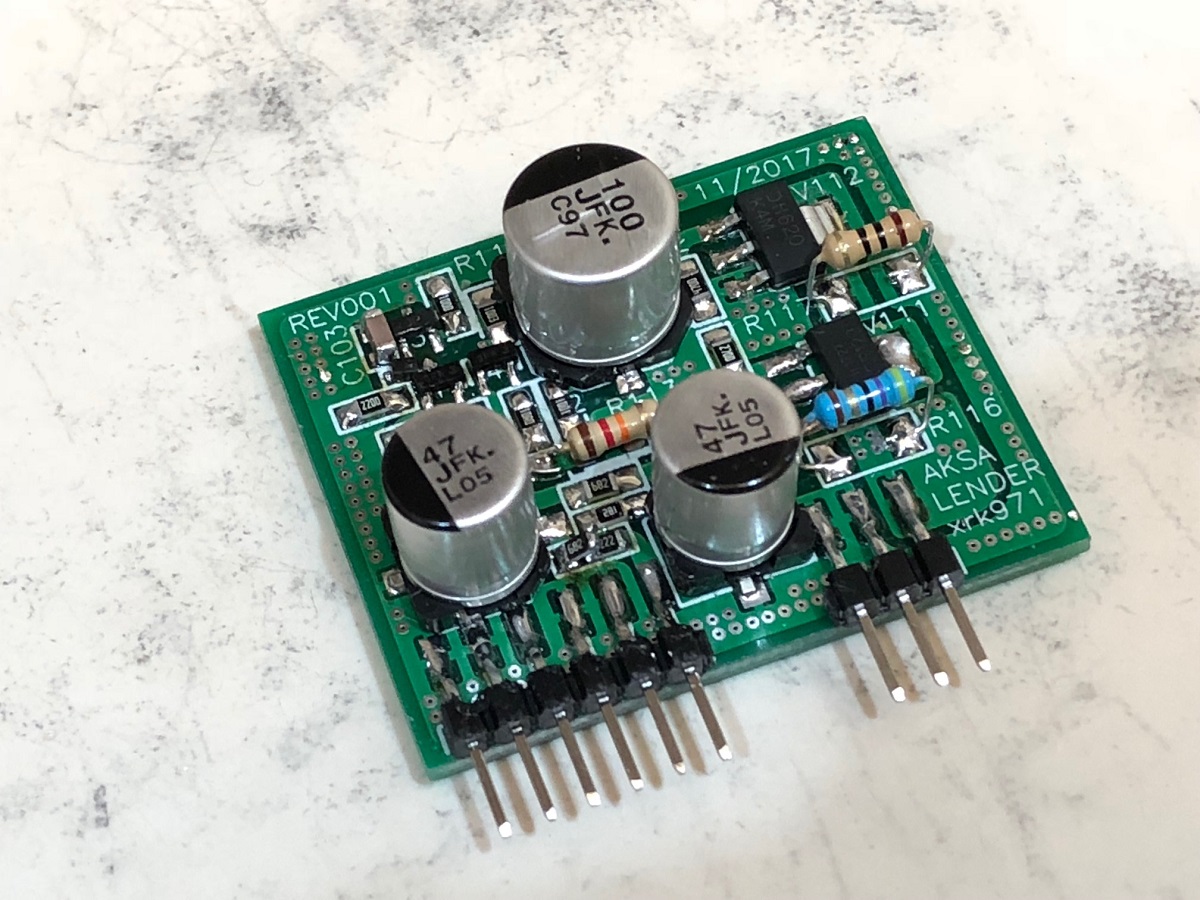
Cloesup of SMT board:
Here are measurements from the TH and SMT boards:
TH has 0.001% THD for 20vpp into kohm load:

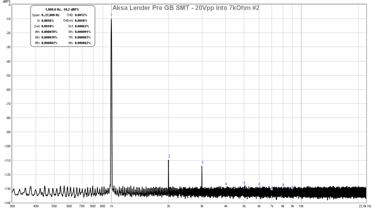
SMT has 0.0012% THD for 20Vpp into 7kohms:
Edit Mar 3, 2018. BOM and Schematics for the GB PCBs here
http://www.diyaudio.com/forums/anal...ender-preamp-40vpp-output-48.html#post5360015
I had been complaining to Hugh Dean (AKSA) a few weeks ago about the dearth of simple, but nice sounding preamps with muscle to swing 40 volts peak-peak. Why would we need a preamp to have so much muscle? There are quite a few unity gain current amps out there in want of a high quality preamp that can swing their outputs beyond the usual voltage limitations of a +/-15v rail supply. The Pass F4 is one that comes to mind. For the person who likes the sound of opamps (and nothing wrong with that), I recently discovered (a well-known fact by many, invented in the eaarly 1970's) that you can bootstrap an opamp with a pair of TO92 BJT's and 4 resistors to get it to work from +/-44v rails for 70v p-p swing. That was an eye opener for me, but alas, the sound of an opamp to me, just isn't enthralling. After all, my time to listen to music is limited, and when I do have time, it's SE Class A or nuthin' 🙂
So, Hugh was kind enough to make up a new preamp for me to address this need for a 40v swing SE Class A amp with guts and a nice SE Class A signature, but this time, SE Class A and very low THD. Hugh says the design is inspired by a Lender balanced input stage, but with a few tweaks added by Hugh. It is simple: just 4 BJT's and a CCS, or 5 actives if you count the BSP129 depletion mode MOSFET I employed for the CCS. Although simple, the predicted performance is quite phenomenal. Hugh provided me the basic schematic in LTSpice with a generic 12mA CCS. I had some BSP129's on hand so decided to use them. A DN2540 would also work as well and not require SMT soldering. I could not find readily LTSPice usable models for the BSP129, although a very comprehensive manufacture model is available - I asked for help over in the Software Tools Forum, and Keantoken was kind enough to take the factory model and port it to a easy to use model and symbol for me to plug into Hugh's circuit. So I owe a huge thanks to Hugh for the design, and Keantoken for the BSP129 model porting.
Here is the schematic of Hugh's Lender Preamp. As you can see, it is quite simple and I was able to veroboard prototype it quickly:
Before we go into the implementation, here are some predictions of the performance. I am assuming that the power amplifier input impedance is 27kohm, although 10k still looks very good. First at an output of 4v peak-peak and this is representative of typical very high volume levels one would ever need in a line-level preamp connected to a power amplifier with circa 20dB to 30dB gain. The distortion is exceedingly low in the ppm's and the nice thing is that it doesn't rise with frequency:
Here is the predicted FFT for 20v peak-peak output, a serious level and if driving a buffer power amp, only gets you about 6w rms with 8ohm speaakers, meh... but look at the low distortion figures (0.005%THD, the figures in parenthesis is the one I am using and think it includes THD+N?) and the nice descending higher orders from dominant 2nd order:
So, what if you need to drive 25w rms into 8ohms? Well, you need to swing 40v peak-peak. The predicted THD is still quite low and the harmonic profile is still beautiful with no higher orders going nuts. So this preamp can do it all: works well with normal high gain amps, and with unity gain current buffer amps like MOSFET followers:
For completeness, here is the predicted frequency response and phase. Nice and flat from 10Hz to 1MHz. Phase is very flat too.
Here is my quick veroboard proof of concept build. I am using a simple DC-DC step up converter followed by a CRCRC to get 44.5v PSU rail that is pretty clean, shown is the 12.5mA (125mV over 10ohms) bias setting that I was adjusting using the pot (R15) on the BSP129:
Here is the obligatory scope shot to show that indeed to makes 40v p-p. This was with an initial gain of 4.3x, which I later boosted to about 9.2x for later with still excellent results:
Here is the measured FFT for 1kHz input and 20v p-p output into a 25.3kohm load (27k plus a 10:1 voltage divider comprised of a 22k & 2k2 resistors):
Here is the measured FFT for 5kHz input and 20v p-p output into same load. As you can see, there is no rise in the THD:
The FFT signal looks low because I was using a 10:1 voltage divider to drop the signal to a safe level for the Focusrite 2i4 2nd gen audio interface.
So how does it sound? Well, I only had one channel, so I connected it to both left and right inputs a low-distortion, DC-coupled, current feedback topology(read, neutral in character), commercial headphone amp (Schiit Magni 3) and listened with some DT880-250's and also Status OB-1's. The preamp sounds amazing. Very transparent, no hint of noise, hiss, or hum. Dynamics were outstanding, and in part, the transparency of te M3 allows the nature of the preamp to come through. Cannot comment on soundstage etc as only in pseudo stereo. But I expect that it will not disappoint based on phase margin predictions and THD and noise floor.
Edit Nov 12, 2017: I found a software glitch that caused the 5th and 9th harmonic. New measurements here:
http://www.diyaudio.com/forums/soli...lender-preamp-40vpp-output-4.html#post5242220
4vpp into 25.3kohm:
20vpp into 25.3kohm:
30vpp into 25.3kohm:
I think the measurements speak for themselves, this is a superb measuring and sounding preamp.
Edit Nov 13, 2017: Looking at performance into a lower 3.4k ohm impedance load.
http://www.diyaudio.com/forums/soli...lender-preamp-40vpp-output-5.html#post5242398
Here is FFT for 4v p-p into 3.4kohm load:
Here is FFT for 20v p-p into 3.4kohm load, still very admirable performance:
Here is FFT for 36v p-p into 3.4kohm load, here the H2 and H3 are about the same and any higher in amplitude results in clip:
Here is IMD (DIN standard 250Hz and 8kHz 4:1) for 20vpp into 3.4kohm yields 0.02% IMD:
Here is IMD ((DIN standard 250Hz and 8kHz 4:1) for 20vpp into 25kohm yields 0.01% IMD:
Edit Nov 17, 2017: Here is the final design laid out in SMT with exception of 1 resistor (R10) is a carbon composition and you can find out why here. The feedback resistor is 6k8 and the LTP emitter degeneration resistors are 47R. I am now getting -85dB for H2 and -100dB for H3, and nothing else. It is a superb sounding profile - engaging, great dynamics, full of energy yet natural sounding. Here is 20vpp driving 7kohms. Noise floor is deep deep black with no hint of any mains peaks.
Preamp looks like this:
Other side:
I love how it sounds. Sublime.
Edit Nov 17, 2017 - Bimo requested boosting gain to about 12x and show distortion profile and THD. With 10R degeneration resistors on LTP and 12k carbon resistor on R10, we get this for 20vpp into 7kohms - 0.002%THD and nice profile with only H2 and H3:
For line level driving of typical amps that have some gain, no more than 4vpp will ever be needed and here the FFT and THD for 4vpp into 7kohms we get 0.0011% THD and H2 is only5.7ppm:
Edit Nov 18, 2017 - perhaps the title should be modified to 70vpp? Here is a recent simulation with 100v Vcc showing a nice result for 70vpp output into 10kohm load with a 20dB gain setting on the amp. THD is predicted to be 0.0077% with a nice profile.
To do this requires changing the input LTP devices to MMBT5401 (or 2N5401 for through hole builds) and adjust R4b to 17k to keep 2.5mA current in the LTP. Change the degen resistors R5/R6 to 3.3ohms, and R9 to 100k. Make sure all electrolytics are revised to handle max voltages of 100v on rail and output node and 63v elsewhere.
Here is schematic v2.0 for the HV amp:
Group Buy here:
http://www.diyaudio.com/forums/group-buys/315521-aksas-lender-preamp-40vpp-ouput-gb.html#post5261067
Edit Dec 10, 2017: GB boards verified to be working. Here is MB with TH and SMT daugterboards installed.
Cloesup of SMT board:
Here are measurements from the TH and SMT boards:
TH has 0.001% THD for 20vpp into kohm load:
SMT has 0.0012% THD for 20Vpp into 7kohms:
Edit Mar 3, 2018. BOM and Schematics for the GB PCBs here
http://www.diyaudio.com/forums/anal...ender-preamp-40vpp-output-48.html#post5360015
Attachments
-
 Lender-Preamp-Aksa-Schematic-v5.png25.4 KB · Views: 33,380
 -
 Lender-Pre-20vpp-5kHz.jpg120.6 KB · Views: 17,073
 -
 Lender-Pre-20vpp-FFT.jpg128.7 KB · Views: 19,370
 -
 40vpp-oscope-screenshot.jpg267.9 KB · Views: 22,777
 -
 Lender-Pre-Veroboard-Test-bias-setting.JPG159.2 KB · Views: 17,389
 -
 Lender-Preamp-Aksa-FR-20vpp-27k.png27.3 KB · Views: 19,185
 -
 Lender-Preamp-Aksa-FFT-40vpp-27k.png52.7 KB · Views: 19,283
 -
 Lender-Preamp-Aksa-FFT-20vpp-27k.png45.9 KB · Views: 21,731
 -
 Lender-Preamp-Aksa-FFT-4vpp-27k.png36.7 KB · Views: 19,863
Last edited:
Try using the Blackman-nuttall window selectable in the FFT dialog. It will push your drift floor down a bit more. You could also make C1-C4 100F.
Try using the Blackman-nuttall window selectable in the FFT dialog. It will push your drift floor down a bit more. You could also make C1-C4 100F.
In LTSpice or in real circuit? I don't have 100F caps so probably the simulation 🙂
Thanks for the tip. I was trying to model the as-built components.
Nice work X, as always. Do not forget that some of those amplifiers you mentioned have mosfets on the input which do not like to exceed 20 volts on the gate, hence the zener diodes protecting the gate.
Thanks X,
I never expected the THD would be so low in this circuit. It really is surprising!
Thanks for all the work,
Hugh
I never expected the THD would be so low in this circuit. It really is surprising!
Thanks for all the work,
Hugh
Thanks X,
I never expected the THD would be so low in this circuit. It really is surprising!
Thanks for all the work,
Hugh
No, thank YOU, Hugh for giving us such a nice design to play with!
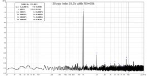
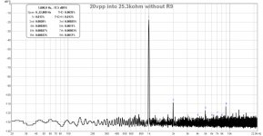
You never expected the THD to be so low, and I tried your suggestion of removing R9 to see what happens. Here is an FFT with R9 and without it - I literally cut the leg of the 68k resistor in the live circuit so that I could see definitively the effect in real time while watching the FFT. For 20vpp into 25.3k load, the THD was 0.0058% with R9 and 0.0035% after I cut R9 to remove it. The profile is still H2 dominant but lower overall THD. However, it places the level of the H5 and H9 higher relative to H2, albeit the levels of all the distortion is quite low, near the -130dB noise floor of the Focusrite.
Let me spend some time listening to it without R9 and will let you know what I think of the sound quality subjectively.
FFT with 68k R9 in place:
FFT with R9 snipped off:
Attachments
Fascinating X! I would expect that leaving R9 in will sound markedly better.
This tells us something significant but until you assess the SQ I won't say!
Thanks so much for the terrific measurements.
HD
This tells us something significant but until you assess the SQ I won't say!
Thanks so much for the terrific measurements.
HD
Last edited:
Beutiful result!
Can someone explain why we choose P devices in the IPS?
I asked same question 3 days ago under the link below where a similar schematics was presented by Zen Mod (~4 posts above mine), but no answer yet.
About possible Babelfish J interest
Can someone explain why we choose P devices in the IPS?
I asked same question 3 days ago under the link below where a similar schematics was presented by Zen Mod (~4 posts above mine), but no answer yet.
About possible Babelfish J interest
Output is low impedance (<5R), but limited to 12mA CCS. This can nicely drive a small output stage, single ended or PP. The buffer, Q4, could be made a FET or even increase current to 30mA. That would boogie!
UT, if you use pnp for the LTP, it mandates npn VAS, and my experience is that npn VAS has lower parasitics and greater GBW than pnp in the same role.
HD
UT, if you use pnp for the LTP, it mandates npn VAS, and my experience is that npn VAS has lower parasitics and greater GBW than pnp in the same role.
HD
Last edited:
Also generally PNP in LTP gives lower current noise, doesn't it? Reason why a lot of phono preamps were designed that way. Not sure if it matters here with signal levels involved. Ofcourse, as Hugh said, it also allows for NPN VAS which is just what you want for its desired characteristics.
I do not think it would be audible, but why is there that ninth of some 0.002%?? The 9th is usually 110 - 130 dB below the fundamental. Just curious where it is created.
Yes, and the 5th is way too high - maybe some measuring setup artifact ?...why is there that ninth ...
Using PNP LTP in single rail PSU circuit is good for the PSRR too.
Anyway I'd lose Q4 and unstrangle Q3, let the LTP breathe, change CCS and at least bootstrap the tail of of the LTP. Gain should be higher so that weaker sources and/or quieter recordings can bring enough voltage swing at the output. Drive capability should stay about the same.
Roughly, something like this (R1/R2 divider might need some adjusting to ensure symmetrical clipping and freq.compensation should be checked in vivo. Practical details like PSU bypassing and similar are logical addition) :
Attachments
Last edited:
I'm wondering where the 5th and 9th are from too as not in sim. I should change audio interface and PC to see if it clears up.
Juma, thank you for the suggested schematic. I don't believe it is the same topology anymore though. Have you simulated it yet? Looks interesting. It could be a headphone amp with a larger C2 and higher bias, as could Aksa' circuit.
This now seems perfectly clear and a great reason. I have wondered myself.
Juma, thank you for the suggested schematic. I don't believe it is the same topology anymore though. Have you simulated it yet? Looks interesting. It could be a headphone amp with a larger C2 and higher bias, as could Aksa' circuit.
...if you use pnp for the LTP, it mandates npn VAS, and my experience is that npn VAS has lower parasitics and greater GBW than pnp in the same role.
This now seems perfectly clear and a great reason. I have wondered myself.
Last edited:
Sorry but no, I only built it. Yes, I know that these days simulation is more valuable than the real build but I'm an old-fashioned guy... 🙂... Have you simulated it yet? ...
Actually, that sch. is part of the power amp I made some time ago (imagine one pair of Lateral MOSFETs added at the output, with one LED between the Gates to bias them).
Member
Joined 2009
Paid Member
I looked at a similar topology many years ago but never built it (yet) TGM4 amplifier
However, what is shown in post#1 is not quite the Lender circuit. The original circuit, 'invented' by Rudolph Lender when he was at Motorola uses a different arrangement with two transistors. I do remember asking Hugh about it too...
However, what is shown in post#1 is not quite the Lender circuit. The original circuit, 'invented' by Rudolph Lender when he was at Motorola uses a different arrangement with two transistors. I do remember asking Hugh about it too...
Gareth,
Tried the Lender, simulated it also. No OLG advantage over a single ended drive to a stock common emitter VAS, and no discernible advantage sonically. However, it does combine some elements of CM, tending to force current balance in the LTP by adjusting VAS current. But this may not be very useful if the VAS current is fixed anyways, as it normally is.
Cheers,
Hugh
I looked at a similar topology many years ago but never built it (yet)...
However, what is shown in post#1 is not quite the Lender circuit. The original circuit, 'invented' by Rudolph Lender when he was at Motorola uses a different arrangement with two transistors. I do remember asking Hugh about it too...
Agreed, hence which is why I said "inspired by" Lender. Nice amp design the TGM4, what does TGM stand for?
Last edited:
- Home
- Source & Line
- Analog Line Level
- AKSA's Lender Preamp with 40Vpp Output