Hi Gable,
We are going to have to ask JPS64 what parts those are. I don’t see it in any of my BOMs either. I think you helped me to make a BOM/shopping cart for Alpha 20 way back when?
I think these might be them:
1001-11, tinned solder terminal | Burklin Elektronik
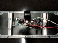
Getting closer to a working amplifier, I hope 🙂
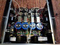
Although it's a large 4U 400mm case, there's not much room left.
Small detail, I've put thermally conductive paste between the two heatsinks (each side has two heatsinks) and also the frontpanel.
So the frontpanel and the four heatsinks become one radiator.
The next step is installing the backpanel with softstart and DC protection on it.
Attachments
Danny!
Super nice.
I am planning a 5U/400 UMS chassis myself for the Alpha 20 then Alpha Nirvana.
Best,
Anand.
Super nice.
I am planning a 5U/400 UMS chassis myself for the Alpha 20 then Alpha Nirvana.
Best,
Anand.
Yes, that’s it. Are they available in the US?
Not that I've been able to find unfortunately. I looked through their catalog a bit last night, they have some interesting terminals, similar to the one in the render.
I think Buerklin will ship to the US, I'll try to confirm.
Wow Danny!!
Truly a monster ALPHA20 your building, looks great 🙂
Good tip applying heatsink compound between panels.
Looking forward to seeing more of your progress......
Truly a monster ALPHA20 your building, looks great 🙂
Good tip applying heatsink compound between panels.
Looking forward to seeing more of your progress......
Thanks!
You think that a 4U/400 case is large until you try to put everything in,
always buy the larger case when in doubt 🙂
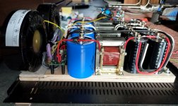
Some more details,
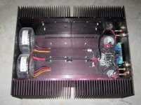
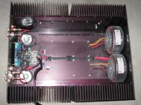
the transformers rest on the wooden multiplex but are fixed with bolts to the frontpanel,
the transformers are sandwiched between rubber washers on the bolts.
The mains goes under the wooden multiplex in which I've routed a channel, coated with aluminum paper and connected to earth.
You think that a 4U/400 case is large until you try to put everything in,
always buy the larger case when in doubt 🙂
Some more details,
the transformers rest on the wooden multiplex but are fixed with bolts to the frontpanel,
the transformers are sandwiched between rubber washers on the bolts.
The mains goes under the wooden multiplex in which I've routed a channel, coated with aluminum paper and connected to earth.
Hi Danny,
Good idea to employ the front panel as radiator. I did not add thermal compound on mine, also a 4U but 300mm single UMS heatsink on Dissipante case. The front panel gets quite warm and probably contributes maybe 10% of the cooling.
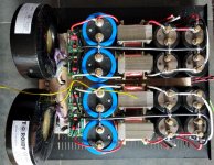
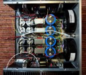
Your build looks very impressive. That’s one of the most manly-man PSUs I have seen! Complete with active bridges and big iron CLC.
Looking forward to your listening impressions. What voltages and bias currents are you set up for? Is this a 4ohm capable Alpha?
Good idea to employ the front panel as radiator. I did not add thermal compound on mine, also a 4U but 300mm single UMS heatsink on Dissipante case. The front panel gets quite warm and probably contributes maybe 10% of the cooling.
Your build looks very impressive. That’s one of the most manly-man PSUs I have seen! Complete with active bridges and big iron CLC.
Looking forward to your listening impressions. What voltages and bias currents are you set up for? Is this a 4ohm capable Alpha?
I also shifted the PCBs one cm more to the frontpanel than in dead center,
this to distribute better the heating of the two mosfets (taking in account the frontpanel as radiator)
Yep, the 4R version (1.8k FB shunt resistor), I'm obliged after all the simulations I did 😉
The rails will be 24vdc, bias 1.9A, higher damping factor with NFB resistor divider trick.
I'm also eager to hear it play, hopefully next WE
That’s 46w dissipation per MOSFET. About same as what I am running on Alpha Nirvana (+/-28.5v and 1.7A). My 4Ux300mm case runs at 55C to 57C with 21C ambient temps. The Fairchild FQ MOSFETs are good here.
You have 400mm case so should be cooler and about perfect.
You have 400mm case so should be cooler and about perfect.
Danny,
Beautiful work, elegant and quite compact for all the bits, including the four inductors.
You are a master 'wire fitter'.
How does the sound compare to other amps you have?
You could do with more power, of course, that was the intention with the 40W Nirvana.
ciao,
Hugh
Beautiful work, elegant and quite compact for all the bits, including the four inductors.
You are a master 'wire fitter'.
How does the sound compare to other amps you have?
You could do with more power, of course, that was the intention with the 40W Nirvana.
ciao,
Hugh
Hi Hugh,
The sound will hopefully be for next WE,
I'm still busy with assembling the backpanel that holds the soft start and DC protection.
Grts,
Danny
The sound will hopefully be for next WE,
I'm still busy with assembling the backpanel that holds the soft start and DC protection.
Grts,
Danny
I'm building myself a new Alpha, and it's time for me to measure all my ksa992's to match a few pairs. I have a couple quick questions.
Do we only need to match of hfe?
Is there an ideal range to try and find matches in?
I have a bunch of 992s so I should hope I can get good matches.
Thanks!
Gable
Do we only need to match of hfe?
Is there an ideal range to try and find matches in?
I have a bunch of 992s so I should hope I can get good matches.
Thanks!
Gable
No, you don't need to match hfe.
BUT if you wish to, here is the procedure:
1. Select two transistors with an hfe within say about 5, eg, 345 and 350.
2. Match at least ten of these pairs for your required two for a stereo AN. But now you will need to match Vbe, voltage from base to emitter, so they match too.
You need to set up a jig which passes 2mA stage current into a diff pair, using a bipolar +/-15V supply, with the two bases connected to ground, the collectors to the -Ve rail, and the two connected emitters connected to a supply 7.5k resistor at the +Ve rail.
To fully match two bipolar transistors, you should match not just hfe, the beta, but also the Vbe voltage so they match also under load.
Hugh
No, you don't need to match hfe.
BUT if you wish to, here is the procedure:
1. Select two transistors with an hfe within say about 5, eg, 345 and 350.
2. Match at least ten of these pairs for your required two for a stereo AN. But now you will need to match Vbe, voltage from base to emitter, so they match too.
You need to set up a jig which passes 2mA stage current into a diff pair, using a bipolar +/-15V supply, with the two bases connected to ground, the collectors to the -Ve rail, and the two connected emitters connected to a supply 7.5k resistor at the +Ve rail.
To fully match two bipolar transistors, you should match not just hfe, the beta, but also the Vbe voltage so they match also under load.
Hugh
Excellent, thank you Hugh!
Hi, I built the Alpha 20 a while back according to the schematic. I love the sound of the amp, but there is a lot more gain than I need. Does changing resistors for lower gain effect the sonic signature of the amp? In particular, I don't want to lose any of the bass response and punch.
Thanks
Thanks
Yes AlJordan,
simply increase the shunt fb resistor the one which bear straight onto the large electro shunt cap. Increase it from 1k to 1k5 will reduce gain from 22 down to 14.
No other changes.
HD
simply increase the shunt fb resistor the one which bear straight onto the large electro shunt cap. Increase it from 1k to 1k5 will reduce gain from 22 down to 14.
No other changes.
HD
Hi X,
I have an unused chassis available and was wondering if it would be suitable for a stereo ABBB or Nirvana?
The chassis has (4) 8.0625" H * 10.0625"L* 2.875"Thickness (.375" base plate + 2.5" fins). (2) heatsinks per side.
Regards,
Cambe
I have an unused chassis available and was wondering if it would be suitable for a stereo ABBB or Nirvana?
The chassis has (4) 8.0625" H * 10.0625"L* 2.875"Thickness (.375" base plate + 2.5" fins). (2) heatsinks per side.
Regards,
Cambe
Attachments
- Home
- Amplifiers
- Solid State
- Aksa Lender P-MOS Hybrid Aleph (ALPHA) Amplifier