Just to recap and make sure I've got everything nailed down properly for the 4R version, can anyone confirm the changes in the schematics?
Thanks
Do

Thanks
Do
That looks good Pinnocchio. Please note that with 2k2 feedback shunt resistor gain is about 20dB so you will need a Preamp to drive it to clipping, or of your DAC puts out at least 1.74v.
Last edited:
YES Do all correct and endorsed by X and by me.
There must be a lot of 4R high quality speakers..... maybe ribbon tweeters?
HD
There must be a lot of 4R high quality speakers..... maybe ribbon tweeters?
HD
Yep Do, that's it.
If you need more more gain you can change the shunt fb to 18k + 68uf,
clipping at 1.45 Vin
Grts,
Danny
If you need more more gain you can change the shunt fb to 18k + 68uf,
clipping at 1.45 Vin
Grts,
Danny
Yep, and double 10" woofers.There must be a lot of 4R high quality speakers..... maybe ribbon tweeters?
I can use the current, but not much voltage 🙂
Ah, yes, audio of solar plexus??
You need Class D for the woofers, Danny, and the ALPHA for mids and tweets.
What are you doing about the crossover? This is a huge problem for musicality. Very few active crossovers sound really good, even the best of them. Most of them ICs, too, and the two issues are very high global fb and their power supplies. I am discouraged by active crossovers, and also try to get my customers to use passive crossovers on their speakers, preferably third order with good Zobels across the drivers.
Cheers,
Hugh
Yes Hugh, that's the same reason I stay away from active crossovers for mid and high.
Too much additional active elements (AD/DA converters, and their PS) to control,
they become often the limiting element in the system and take something away from that ultimate transparency.
The best solution I've seen is the one that Troels implemented: semi active(digital), semi passive
Grts,
Danny
My Speakers are Troels ATS-4. Amazing speakers but requires a little power on the bass side.
Thank you all for checking the 4R schematic!
Do
Thank you all for checking the 4R schematic!
Do
Hi Diego,
Always a pleasure to chat with another Spanish speaker who writes better English than most English speakers on this forum!! You, Maty Tinman, and many of the European and sub-continent guys are just amazing. I have less ability with other languages than a garden gnome, hats off to you all!
I am uneasy about this method of finding the compensation capacitor too. It sits badly with the usual scientific method in every way. I put it to you that this is the reason this engineering process is also art. There is judgement involved, like designing the fb for an electric power steering system for an auto. It is empiricism, not the scientific, mathematic approach.
It is almost impossible to be objective about the subjective. That is the problem......
Try it. You will hear the changes. BTW, I have used the Rush cascade for many years, it has very low phase shift and blinding speed. I like your circuit, Diego, it's masterly.
Ciao,
Hugh
Very grateful for your reply, Hugh.
I will try to find that sweet spot in some of my circuits, if it is perceptually possible for me.
I find it very intriguing that a capacitor that is supposed to act well outside the audible band, produces noticeable perceptions within it. That's crazy!!!.
In your amplifier, that capacitor would be affecting notably around 300 KHz or more. This would be more than one and a half decade above the highest audible frequency, so that the alteration of the phase of an audible signal at the upper limit of the band would not suffer important changes.
In my simulations, the effect of that capacitor becomes noticeable only when it is affecting already close to the upper limit of the audible band. This is reflected, when analyzing a step signal, in total absence of overshoots. The case is very different when the capacitor is of very little value or nonexistent.
It is very striking that both THD and an FFT analysis show virtually no changes. Something would seem to vary in the IMD, but I am somewhat far from being able to associate these changes with what could be perceived.
The only thing that occurs to me, for the moment, as a premature explanation is in the incidence of the transient state of that capacitor in the presence of relative high frecuency and very strongly damped signals, contemplating your comment about certain musical programs (large orchestra) where its incidence could be most noticeable.
Best regards
Last edited:
Hi Diego,
I also tried to find something in the simulations for the compensation cap in this post.
But the FFTs kept saying: nothing to see here, please move on.
Only with unrealistic capacitive load (1uf) I got some overshoot.
So the Alpha is very stable even with different compensation caps and capacitive loads,
still the compensation cap has such a profound effect on the imaging stage.
I'll do it be listening to different values.
Grts,
Danny
possible FQA38N30 or FQA32N20C
Hi to All.
I'm still following with huge interess. 🙂
Alibear was asking for ON Semis- so i ask myself too: why a Uni Fet and not a Q-Fet in N Channel?
And FDA has much lesser gm(S).
The above named parts are much closer to FQA36P with S:19,5 (20 and 24)
Is that a good choise too for reg. ALPHA?
HTML:
Question please, I have used FQA36P15 and FDA38N30 mosfets as suggested by Hugh right at the start of the thread. I need to get some more but my usual wholesaler is out of stock of the FDA38N30. Can you tell me is FQA40N25 a good substitution as those are in stock.I am not very familiar with Fets.Hi to All.
I'm still following with huge interess. 🙂
Alibear was asking for ON Semis- so i ask myself too: why a Uni Fet and not a Q-Fet in N Channel?
And FDA has much lesser gm(S).
The above named parts are much closer to FQA36P with S:19,5 (20 and 24)
Is that a good choise too for reg. ALPHA?
Good to hear from you BanglaH,
Did you ever order an Alpha 20 board? I have some left from GB2 if you are interested - I know you will enjoy it.
Did you ever order an Alpha 20 board? I have some left from GB2 if you are interested - I know you will enjoy it.
I find it very intriguing that a capacitor that is supposed to act well outside the audible band, produces noticeable perceptions within it. That's crazy!!!.
I still get a lot of raised eyebrows from objectivists who believe that if you can hear it, that it must be measurable. I still believe in measurements of course, as you may have seen, I don't think anyone else on DIYA posts as many measurements of their amps and speakers, but after hearing the changes in soundstage and spatiality with my own ears, I think we have just not found the right thing to measure. I believe it may have to do with the phase relationships of the signal itself at the tens of microseconds timescale. Our hearing may stop at 20kHz, but notice that the small mm scale folds on our earlobes are there to impart asymmetric phase shifts to the sound to allow us to localize even with one ear. What is the effect of a 5mm fold on the phase shift of an audio signal? 342m/s speed of sound, 0.005m distance, time=0.005m / 342m/s = 14.6us or 68.4kHz. Disturbance of microseconds in phase matters.
I still get a lot of raised eyebrows from objectivists who believe that if you can hear it, that it must be measurable. I still believe in measurements of course, as you may have seen, I don't think anyone else on DIYA posts as many measurements of their amps and speakers, but after hearing the changes in soundstage and spatiality with my own ears, I think we have just not found the right thing to measure. I believe it may have to do with the phase relationships of the signal itself at the tens of microseconds timescale. Our hearing may stop at 20kHz, but notice that the small mm scale folds on our earlobes are there to impart asymmetric phase shifts to the sound to allow us to localize even with one ear. What is the effect of a 5mm fold on the phase shift of an audio signal? 342m/s speed of sound, 0.005m distance, time=0.005m / 342m/s = 14.6us or 68.4kHz. Disturbance of microseconds in phase matters.
Not all noise is bad let's add some good noise!
Harry gets a "criteria" & Claude gets a "limit"
Audio specifications come with conditions ,to understand the conditions you must first understand the tests.
Last edited:
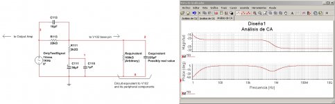
The simplest technical explanation that I find at the moment to the necessary tuning of C113 to optimize spatial aspects, is that it is due to the existence of an equivalent circuit (mostly composed of R and C) in derivation and that is observed in parallel to the components R111 and C111. That equivalent circuit is that reflected by the base of one of the transistors of the LTP pair (the one on the right of the LTP). It would be a situation similar to the calibration operation of an oscilloscope probe, where physical and parasitic capacities have to be compensated, so that the phase of the signal fed from the output of the amplifier does not suffer any modification.
It is the explanation that most convinces me and technically that can be measured.
Diego,
I love the way you tease the ideas out of this conundrum!! No problem could resist your careful exploration, possibly even space travel!
I am a farmer's son, much happier with my feet on the ground. I urge you strongly to take any amp - my golly, even a Blameless - and then identify the compensation cap and start to play with it, as a cat with a mouse. Try a variety of caps, too, of the same value. You will be astonished with the entire effect across a wide frequency range, it defies logic doesn't it?
It occurs to me that if the FFT and the THD is hardly changed with Lag Comp changes, we are not measuring the correct parameters. I believe it's related to phase shift, and that too is related to global feedback. If you could resolve this age old audio argument, you would be doing the industry a favour. Mind you, if you get the incorrect answer, the marketing department will not love you.......
Ciao,
Hugh
Diego,
I love the way you tease the ideas out of this conundrum!! No problem could resist your careful exploration, possibly even space travel!
I am a farmer's son, much happier with my feet on the ground. I urge you strongly to take any amp - my golly, even a Blameless - and then identify the compensation cap and start to play with it, as a cat with a mouse. Try a variety of caps, too, of the same value. You will be astonished with the entire effect across a wide frequency range, it defies logic doesn't it?
It occurs to me that if the FFT and the THD is hardly changed with Lag Comp changes, we are not measuring the correct parameters. I believe it's related to phase shift, and that too is related to global feedback. If you could resolve this age old audio argument, you would be doing the industry a favour. Mind you, if you get the incorrect answer, the marketing department will not love you.......
Ciao,
Hugh
Hugh:
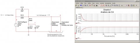
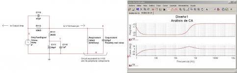
This is how I visualize the tuning process at the optimum value of C113 and, in addition, why it would be necessary to do so.
The base terminal of V102 plus some of its associated components could be simplified to a very simple equivalent circuit: mostly composed of an R and a C, both in parallel. The exact value of R I do not know it in that scheme, although normally it is not a very low value. In addition, its value (while remaining within a wide margin) is not determinant in what I need to demonstrate.
Although the value of C113 is imposed mainly for reasons of stability, it could be tested if, additionally, a feedback signal phase can be achieved without major changes in a wide range of frequencies.
In the tests I have uploaded, it can be clearly seen that a theoretical value of 22 pF for C113 could correspond to an equivalent value of Cequivalent of 225 pF. That is, very close to the reciprocal ratio of the values of the feedback network: C113 = (2k2 / 22K) x Cequivalent.
I think, besides that a concrete and real value of Cequivalent can be measured without problems (that would be very simple: we look for the attenuation point of -3dB, injecting a test signal from a fixed series impedance towards the base of V102, after disconnecting the entire feedback network.
See in all the graphs how the phase curves vary, altering the value of C113. Only one of them remains flat, when there is perfect compensation, depending on their associated impedances.
Regards
Attachments
In the previous simulations you will see that greatly altering the value of Requivalent does not have an important impact on the final results. I have tested values from 22K to several Megas and, to the conclusion that I arrived is that only Cequivalent is the most dominant parameter 🙂.
Regards
Regards
- Home
- Amplifiers
- Solid State
- Aksa Lender P-MOS Hybrid Aleph (ALPHA) Amplifier