I am busy with the amplifier enclosures, I work on two enclosure the same time. One for the M2 and one for this amplifier.
However, it goes very slow some days I can do nothing someday just a bit because of my health situation. Also, I live in an apartment for every hole drilling I have to go down not to disturb my neighbors. Pictures were made on the balcony.
These will be the Alpha case, it needs a faceplate, bottom etc. I am not sure if I use that stainless for the top, I have second thoughts about.
I will see I have to find a store where they cut material into size.
First I will try 20-0-20VAC transformer if the heatsink can handle more power at summer maybe I will increase the rail voltage.
Maybe until the end of summer, I will finish it.
Looking good! I understand your pain with not having any shop/garage etc where to build.. There has bees quite a drilling with the top plates!
I have also used the Juma cap Mx on my MoFo at 1.7amps without issue. It was a P2P cap Mx though so maybe there may be an issue with the PCB implementation.
hello x, has someone/you tested it with linear psu and some other amp drawing similar currents?.
As per my knowledge, James Hill used the same Juma CMX PCB w/o issue except he was none too happy with the heat in his set up.
regards
Prasi
Hi Prasi, I had linear PSU and 1.93A per channel. It was working, but generated heat MUCH more than Alpha itself. Got too little hours to play it, that I can't tell was there any sonical differences vs CRC-supply. It was very quiet tough.
Can anyone confirm if the Mr Evil cap Mx ha a lower drop out voltage and hence, less heat? I am looking into a circuit designed by Keantoken for a low dropout soft start and cap Mx. Hopefully around 0.6v to 1.2v dropout.
Hi, back from holidays so will have to get going again with the Alpha.
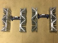
After lots of experimenting with heat sinking, both passive and fan assisted, I decided to go the passive route . I decided on a mono block construction to try to avoid large size and weight. The plan is to mount the Alpha PCB at right angles between the heat sinks that will form the sides. Due to the height of the sinks,150mm, I am thinking transformer, rectifier, capacitors etc. on the base and then an aluminium sub floor with the Alpha above. I think this will give good protection from any noise radiated from the toroid.The outside dimensions will be 300 x 300 x 150.
The heatsinks I have are not new and require cleaning, also some milling to accommodate the bottom and top cover.I don't yet know wheather to have them anodised a different colour (depends on cost ).
Gabriela, I think your cases look great, but I have not copied them,I have been considering this for a while, hope you understand.
Best regards
Alan.
Attachments
Welcome back, Alan. Your setup also uses this popular pick diode heatsink. That must be some diode. Looks very nice and I am sure that the heatsink is quite sufficient.
Rds on mosfet datasheet sets voltagedrop Evil capmx, plus what you add for various reasons, for example you want rails equal or unequal (rds on difference positive rail Pmos and negative rail Nmos), or for example you have 500mv ripple prior to capmx that you should add to voltage drop capmx with trimmer, for capmx not to dropout. It is in that thread also 4700uF output cap is equal to 100uF outputcap according to MrEvil, if I remember correctly and the 100nF bypass cap over outputcap increases outputripple, doesn't decrease, so deteriorates output, doesn't improve output. (Kneteman??? and Allo do have that bypasscap on pcb and both populate position, but Kneteman??? also mentioned he measured deterioration, so maybe he removed part again for pcb he uses?
Can anyone confirm if the Mr Evil cap Mx ha a lower drop out voltage and hence, less heat? I am looking into a circuit designed by Keantoken for a low dropout soft start and cap Mx. Hopefully around 0.6v to 1.2v dropout.
from memory, you had built esp cap mx and not too satisfied with results. I don't know if that would be suitable here.
since ESP doesn't sell PCB for the cap mx, I wonder if I am allowed post a design here. If not, request mods to delete the post😱.
ESP suggests to build it p-2-p as its very simple one.
regards
Prasi
Attachments
Where do you guys get those heatsinks?
We would all like to know. Apparently from eBay but what model number to search for etc? IIRC, from MoFo thread, Michael Rothatcher said they are available new from Mouser etc but price is rather high.
Rds on mosfet datasheet sets voltagedrop Evil capmx, plus what you add for various reasons, for example you want rails equal or unequal (rds on difference positive rail Pmos and negative rail Nmos), or for example you have 500mv ripple prior to capmx that you should add to voltage drop capmx with trimmer, for capmx not to dropout. It is in that thread also 4700uF output cap is equal to 100uF outputcap according to MrEvil, if I remember correctly and the 100nF bypass cap over outputcap increases outputripple, doesn't decrease, so deteriorates output, doesn't improve output. (Kneteman??? and Allo do have that bypasscap on pcb and both populate position, but Kneteman??? also mentioned he measured deterioration, so maybe he removed part again for pcb he uses?
Is there a summary in the Mr Advil cap Mx thread as to what optimal set of components to populate the PCB with?
Where do you guys get those heatsinks?
hello keantoken,
something similar available in India. These are probably very old designs that were specifically meant for TO-3 as I see such heatsinks on the back of many industrial equipment.
Last edited:
I Purchased these heat sinks for my MoFo from this eBay seller:
Large Reclaimed Extruded Aluminum Heatsink 11"x6.75"x3.1" Audio Amp Heavy Weight | eBay
Regards,
Vunce
Large Reclaimed Extruded Aluminum Heatsink 11"x6.75"x3.1" Audio Amp Heavy Weight | eBay
Regards,
Vunce
I tried posting links, but those links had too many key words and other texts.
here is the google search for the website
perfectmetal - Google Search
here is the google search for the website
perfectmetal - Google Search
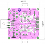
I don't think any component is very important in capmx, but the leds are not just lights to show capmx has power on Evil capmx 🙂
We would all like to know. Apparently from eBay but what model number to search for etc? IIRC, from MoFo thread, Michael Rothatcher said they are available new from Mouser etc but price is rather high.
Newark link:
http://www.newark.com/aavid-thermalloy/db120-20/heat-sink/dp/10WX1014
Quite expensive.
Thanks for the welcome X, grandchildren loved Disney Orlando, a very special place but quite tiring for an old chap like me but wouldn't have missed the wonderment in their faces for the world.
I was fortunate enough to acquire the heatsinks from low voltage high current rectifier cabinets that were being scrapped. They were used for depositing copper on cylinders for the gravure printing industry. Due to the hostile environment they were used in there is some corrosion on them, so quite a bit of cleaning up to do. If that works out well I will see how much the cost is to have them anodised. Two linked together with copper plate will I think be more than ample for each FET.
Great thread.
Best regards
Alan
KT, I bought the same heatsinks described here for my MoFo build. Got them from a vendor on AliExpress, 15usd each, the catch was the shipping, still cheaper than Newark or Mouser
heatsink passive
https://www.fischerelektronik.de/home/
black anonized. Many profiles .
BTW got my stereo set almost complete , 2 channel is slightly better, on oscope.
From my exp. fischer does very good heatsinks.
I need some help though can someone explain a sk56 base 10mm vs diy audio 8mm base heatsink
°C/W
300 x 40 x 120 0.40 °C/W diyaudio
300 x 40 x 165 0.31 °C/W diyaudio
300 x 40 x 210 0.18 °C/W diyaudio
fischer sk56 300 x 40 x 100 0.4°C/W
sk56 300 x 40 x 200 0.3 °C/W
Show me how the calculus is done.
I know thermal calc. & in general
Provide calculus please, i haven't bought diyaudio heatsinks.
You'll get a review of sound when ready listening i takes time . Many days
for better review.
I'll compere it against with same type of output type devices amps push pull topology🙂
Dual rail of course.
HD you'll always wondered how it does sound is your ready BTW?
Or are you still gathering parts or finetuning compensation, thermal compensation or locked on doing it at all?
If i'll love the amp, after 150hours i'll put the arduino automated protection on this one.
Reviews been excellent , over to top. More than i ever could ask for the holy grail perhaps,
Thanks to all of the efforts you all done and shared .
Special thanks to team.
You unlock this door with the key of imagination. Beyond that ........................
It's not twilight zone it's diy audio
For all other improments one day maybe to come be done.
With Hockey Pucks on the 0.00.... C/W coolers. Thermal Cut offs . Old beryllium insulator .
If you got dreams just do them.Life to short. In electronics as general, good design & components choice rules applies mostly, so failure can be minimized ,sometimes you get lucky those are valued dreams!
There is nothing wrong with your device set. Do not attempt to adjust the picture. We are controlling transmission. If we wish to make it louder, we will bring up the volume. If we wish to make it softer, we will tune it to a whisper. We will control the horizontal. We will control the vertical. We can roll the image, make it flutter. We can change the focus to a soft blur or sharpen it to crystal clarity. For the next hour, sit quietly and we will control all that you see and hear. We repeat: there is nothing wrong with your television set. You are about to participate in a great adventure. You are about to experience the awe and mystery which reaches from the inner mind to – The Outer Limits😱
- Home
- Amplifiers
- Solid State
- Aksa Lender P-MOS Hybrid Aleph (ALPHA) Amplifier