No worries ... his box awaits him impatiently ...
But I will and want test the amp, before integrating it. 😉
But I will and want test the amp, before integrating it. 😉
it's in my garage ...
I can turn the knobs ... No sound comes out ... 😀😀😀
But now you can spin and enjoy.....😀😉
Fantastic news Fellas!
I just received confirmation that my Akita amp is out for delivery today 😀
It will arrive this afternoon. I still don’t understand how shipping works?? I haven’t received any progress updates since April 15th.
Will keep you posted.....😉
I just received confirmation that my Akita amp is out for delivery today 😀
It will arrive this afternoon. I still don’t understand how shipping works?? I haven’t received any progress updates since April 15th.
Will keep you posted.....😉
Fantastic news Fellas!
I just received confirmation that my Akita amp is out for delivery today 😀
It will arrive this afternoon. I still don’t understand how shipping works?? I haven’t received any progress updates since April 15th.
Will keep you posted.....😉
Hello Vunce,
I'm happy for you ... Enjoy when he's there😉😉
Shipping is a mystery....😀😀😀
Russian Post it is "fantastic"Fantastic news Fellas!
I just received confirmation that my Akita amp is out for delivery today 😀
It will arrive this afternoon. I still don’t understand how shipping works?? I haven’t received any progress updates since April 15th.
Will keep you posted.....😉
Fantastic news Fellas!
I just received confirmation that my Akita amp is out for delivery today 😀
It will arrive this afternoon. I still don’t understand how shipping works?? I haven’t received any progress updates since April 15th.
Will keep you posted.....😉
It is true that the Russian post gave us ... cold sweats ...
I'm happy for you, Vunce!

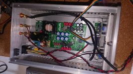
The Akita has landed!
I have a few questions/comments:
Hi Vitaly,
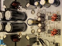
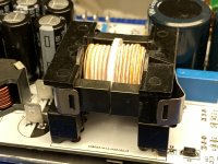
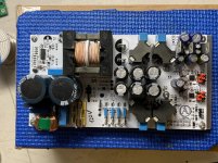
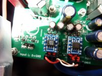
-Should both sides of the inductor cases be soldered to the pcb, they are not secured.
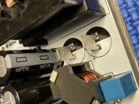
-What is the purpose of the faston tabs at C8 and C9? (Jumper?)
-Can you post details of the input/output/fault/jumper connections for all locations.
Fellow Akita owners,
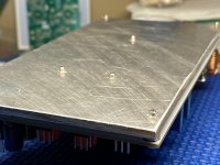
-I wanted to mount this amp module to the base of an aluminum chassis for heatsinking. But the aluminum plate is the exact size of the pcb which leaves no room to drill additional mounting holes. Also the threaded ends of the standoffs extend through the baseplate which doesn’t allow it to sit flat.
-How are you fellas mounting this amp in a chassis? I’m not comfortable using this module with a 44-48vdc psu without additional heatsinking. I have previous experience with the TPA3255 amplifier, she can get HOT!! I really don’t want to pull the baseplate off and make my own. 🙄
I have a few questions/comments:
Hi Vitaly,
-Should both sides of the inductor cases be soldered to the pcb, they are not secured.
-What is the purpose of the faston tabs at C8 and C9? (Jumper?)
-Can you post details of the input/output/fault/jumper connections for all locations.
Fellow Akita owners,
-I wanted to mount this amp module to the base of an aluminum chassis for heatsinking. But the aluminum plate is the exact size of the pcb which leaves no room to drill additional mounting holes. Also the threaded ends of the standoffs extend through the baseplate which doesn’t allow it to sit flat.
-How are you fellas mounting this amp in a chassis? I’m not comfortable using this module with a 44-48vdc psu without additional heatsinking. I have previous experience with the TPA3255 amplifier, she can get HOT!! I really don’t want to pull the baseplate off and make my own. 🙄
Attachments
-
 80361171-F4AC-4921-B55E-CA15A2E33A66.jpg929.3 KB · Views: 231
 -
 9C397D47-4ED3-4FCF-BD05-0FDE20D823AA.jpg749.7 KB · Views: 195
 -
 9F51ED3D-325D-433C-A2D2-E977EA8685C0.jpg674.3 KB · Views: 205
 -
 79674F3A-7A8A-4168-85C7-3469C399687B.jpg728 KB · Views: 187
 -
 F7FB305E-D222-48D7-B06C-8A6F06ED9553.jpg1,014.4 KB · Views: 162
This not problem.-Should both sides of the inductor cases be soldered to the pcb, they are not secured.
yes, this is jumper-What is the purpose of the faston tabs at C8 and C9? (Jumper?)
In this moment amp input in SE config, Input pins - D and B, central pin - GND, A and C pins not used.-Can you post details of the input/output/fault/jumper connections for all locations.
Out - AB one, CD two. positive pins D and B.
Amp really very warm, not hot.
use threaded stands for installation
If need installing in case - use aluminum plate as conductor for drilling hole.
Last edited:

Cool !!!
Akita, has space, the case is suitable and is not too narrow ...
Looks really good .....
I'm really curious what the vu-meters look like ...🙂
Have fun mamocel ....
 😉
😉
I will try .... but it will be on test speakers ... less specifies that my main speakers...😉
Last edited:
do you like the sound with opa627?
Imho, ada4610-2 better
Hello Vitaly,
the OPA627 has a powerful bass and you can hear it too ...
The treble and the middle are covered a bit by the bass ...
Otherwise I can say that the OPA627 is also a good power amplifier ....
Vitaly, in your experience, does a power amplifier take a while to open? Or not...
What do you think about this...
- Home
- Group Buys
- Akita "AllInOne" Amp based on TPA325x PFFB+ and LLC PSU in one board.