In fact, in very few places in a DAC, components with very good tolerance, better than 1%, are really needed. Differential low pass filter is one of these places.
In general, there are two categories of modules in a DAC: those that treat the digital signal and those that treat the analog signal. In addition to these, the sources must be added.
The modules that work with the digital signal support without problems very large tolerances, in some cases even 20% tolerance is indifferent for these modules. The exception is when the conversion is done discretely, not in IC dedicated DACs, but there a multitude of other problems can appear and I will not discuss them now.
Analog modules are somewhat more sensitive to tolerances, but even there usually 1% is sufficient. Only when working with differential signals very good toleranceare are recommended. In fact, there is more a problem of pairing some components, not necessarily tolerance in absolute value.
Anyway, the schemes presented in this topic, until now at least, do not treat the differential signals as they should and the problems generated by the scheme are more serious than the 1% tolerance of the components.
In "classic" LPF schemes, quite high cutoff frequencies are usually used - over 50Khz and if the components have higher tolerances, a desired cutoff frequency of 100Khz (for example) instead of 100Khz will be 95Khz or maybe 105Khz but the behavior in the audio band will be virtually the same with differences that are difficult to even measure and to hear no way, whatever bat ears are used.
And in power supplies, components with very small tolerances are not needed, 1% being already overkill.
The stories with tolerances of 0.1% and even better are just to trick the suckers into paying for products hundreds of times more than they are worth. It's like with single-crystal Cu cables, or with preferential current direction in the cables to obtain sound details a thousand times better, for example.
Last edited:
Any audio design engineer should be aware of the following:
Humans can discern interaural time differences of 10 microseconds or less.[9][10]
https://en.wikipedia.org/wiki/Sound_localization#:~:text=If the ears are located,level differences for higher frequencies.
-------------------------------------------------------------------
Moreover:
Generally speaking, it is thought that the total frequency response of the human ear extends from approximately 16 to 24 000 Hz (Wegel, 1932). However, ultrasound whose frequency ranges up to at least 120 kHz can be perceived by bone conduction (Gavreau, 1948, Pumphrey, 1950, Dieroff and Ertel, 1975).
https://www.sciencedirect.com/science/article/abs/pii/S0378595502007359
-------------------------------------------------------------------
EDIT: Only point is the science is whatever the science happens to be. There should be no need for sarcastic references to "bat ears." Doubtful such sarcastic language would be found in serious scientific and or engineering literature about the limits of human hearing.
Last edited:
I'm not going to stay now to explain what interference means and results when two or more waves overlap.
In all the references above, the high frequencies could not be highlighted directly, but only together with other situations that led to compositions of oscillations.
Anyone can post articles on wikipedia. Until maybe 10-15 years ago, the articles appeared directly, but now they first have to be "verified" by someone, but they can still get there, so wikipedia is not a reliable source for anything except maybe your own information as a starting point to do own studies.
I see you didn't say anything about Cu single crystal wires. How is it with these?
I still remain of the opinion that only the ears of a bat can hear something like this, until I see that people get down with their feet on the ground from the myths created to bring some obscure companies heaps of money.
Why bring up that subject? Is it something you are selling?I see you didn't say anything about Cu single crystal wires. How is it with these?
BTW, we don't need to rely on Wikipedia. ITD has thresholds have been known about for decades. And, yes, it is about time delay differences, not frequency. However, it does appear that phase coherence between stereo channels should to less than a few microseconds of time difference.
Attachments
I'm not selling anything, just maybe information if I have it and it's required.
Regarding single Cu crystal wires, they only came into discussion during meetings with audio enthusiasts and some of them were very pro.
And by the way, if you keep putting references from 100 years ago, add some modern measurements to.
Regarding single Cu crystal wires, they only came into discussion during meetings with audio enthusiasts and some of them were very pro.
And by the way, if you keep putting references from 100 years ago, add some modern measurements to.
The modules that work with the digital signal support without problems very large tolerances, in some cases even 20% tolerance is indifferent for these modules.
I agree, these modules don't require expensive thin film resistors, thick film resistors are generally fine.
In "classic" LPF schemes, quite high cutoff frequencies are usually used - over 50Khz and if the components have higher tolerances, a desired cutoff frequency of 100Khz (for example) instead of 100Khz will be 95Khz or maybe 105Khz
Cut-off LPF frequency tolerance is not an issue at all.
The problem is DIFFERENTIAL properties (CMRR vs F).
Alex.

Please take a look guys ! . https://www.diyaudio.com/community/threads/dac-help.406847/#post-7542193
@bohrok2610 , @altor Hi, do you know if AK4117VF can be used as well in in mode ?. " AK4118, AK4137 and AK4493 can all be used without I2C in pin control mode." . Please take a look . https://www.diyaudio.com/community/threads/dac-help.406847/#post-7542193
Hard to believe this thread came back to the initial topic.
Bogdan if you are still looking for a simple good sounding pin configural solution and you don't need DSD try the proven AD1896.
It works like a charm even on an adapter board and you only need one clock if you use a fixed sample rate output. Jitter reduction is remarkable also. It can't get any simpler.
Hi, do you know if AK4117VF can be used as well in in mode ?. " AK4118, AK4137 and AK4493 can all be used without I2C in pin control mode."
Hi, I have not used 4117, but as I remember it does not have a pin-control mode.
Alex.
Hadn't had much time to test the board, but I get no output from it. I strapped the PDN pin to 3.3V to eliminate the MCP120, which I got wrong. All voltages are fine. There's no activity on the I2S line. There's a 1.6V DC offset at the RX0, not sure if that's correct.
In my experience you need to provide a reset (PDN low) to the AK4118. An RC circuit will probably be OK for testing. Or just a pull-up resistor and a momentary short to GND for an initial test.
1.6V sounds fine for the RX0.
1.6V sounds fine for the RX0.
Is post #71 schematic the one you are using? For RX0 you should set IPS0 (pin 1) & IPS1 (pin 8) to low.
With pin-control (parallel mode) it is best to use pin headers with pull-up or pull-down resistors for all control pins so jumpers can be used for configuration. This makes the board more versatile and avoids possible configuration errors of fixed control pins.
E.g. on my parallel mode AK4118 board I have pin headers on IPS0-1, DIF0-2, OCKS0-1 and CM0-1.
E.g. on my parallel mode AK4118 board I have pin headers on IPS0-1, DIF0-2, OCKS0-1 and CM0-1.
Tried to do a mod on the 4118 and managed to break a pin, and since I only ordered a piece and it's only available from Mouser, I have to wait until I reach the minimum order to get a replacement. Until then I managed to find a DIR9001 transceiver so I'll go with that, at least for now.
Attachments
After building this circuit I'm having issues getting DIR9001 to output data. The error pin is always high. With CKSEL disconnected from ERROR, the clocks are ok but there's no data. The signal from the picture is the input on the RXIN pin, is it a good SPDIF signal?
Attachments
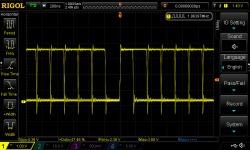
Could be SPDIF. Can't tell for sure. Looks like scope is retriggering so you have more than one sweep superimposed. Also, probe ground may be causing some ringing. To know if its SPDIF would require a single sweep capture of enough data to then decode it. If you scope doesn't support that, then the best way is probably to try a different SPDIF receiver. Do you have any other dac or other device with a SPDIF input?
- Home
- Source & Line
- Digital Line Level
- AK4493 + AK4118 DAC