Super green tape !!! 😀
Thinking this way Eva, my BIG inductor works much better, because it have only 1.3 layers, yes, one layer and some more turns.
And maybe Eddy current my explain the heat.
One from C & D technologies :
* INDUCTOR, 22UH 11A
* Inductor type:Inductor
* Inductance:22µH
* Tolerance, inductance:±10%
* Resistance:0.012R
* Current, DC max:11A
* Frequency, resonant:9.3MHz
* Case style:Radial
* Q factor:64
* Tolerance, +:10%
* Tolerance, -:10%
* Diameter, body:24mm
* Diameter, lead:1.3mm
* Diameter, reel:4.5mm
* Length / Height, external:14.5mm
* Length, lead:10mm
And another from JW Miller / Bourns which I don't know the resonant frequency, but must be in Mhz order (my amp switches 350Khz):
* Toroidal Inductor
* Inductor Type:Toroidal
* Inductance:22uH
* Inductance Tolerance:+/- 15 %
* Current Rating:16.4A
* Series:2300
* DC Resistance Max:0.007ohm
* Package/Case:Radial Leaded
* Leaded Process Compatible:Yes
Both are high current capable and resonable cheap.
But well... For a fisherman line bobin wound with copper wire, my inductor worked nice !!
Amazingly it sounds nice hehehe ! 🙂
Ok, this topic showed me that air core inductors aren't nice. So WHY tripath amp fans like so much air core inductors??? 😱
Humans love non-sense stuff... It's everywhere.
Now seriously speaking: Ready made inductors won't use cores suitable for class D (capable of cool operation under a strong AC flux), so consider buying some T106-2 and T130-2 cores (and maybe some of MPP on the same sizes) from online stores and building your own inductors. I have recently published a post with links to online stores that accept paypal.
Now seriously speaking: Ready made inductors won't use cores suitable for class D (capable of cool operation under a strong AC flux), so consider buying some T106-2 and T130-2 cores (and maybe some of MPP on the same sizes) from online stores and building your own inductors. I have recently published a post with links to online stores that accept paypal.
Attachments
Also consider a material called "Kool mu" or "sendust"... if you can find it... much cheaper than MPP.
I think I'm in love with Eva's hand...
🙂
I think I'm in love with Eva's hand...
🙂
Nah, the hand does not look soo good because I have been doing too much prototyping, I have a couple of broken nails 
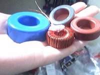
EDIT: The blue one is Arnold A-087059-2, it's 26u MPP. I use these for high voltage class D, they can handle 600 gauss at 50Khz without problem (and required inductance is achieved without too many turns).
EDIT: The blue one is Arnold A-087059-2, it's 26u MPP. I use these for high voltage class D, they can handle 600 gauss at 50Khz without problem (and required inductance is achieved without too many turns).
I'm in love with a woman who knows what MPP core actually means....so I'm in love with my wife. She would sypathize with your nail problem Eva, she does all of our prototyping and then runs the business too.
Bud
Bud
It's risky to generalize about cores, but what I've found in that frequency range is that MPP cores are quite good, but if you want the absolute lowest losses for a given volume, you're better off gapping a high perm ferrite. The desired gap is usually quite small, .003" to .020", and I use a round piece of brass shim on a small motor, and a mix of carborundum powder and water (valve grinding compound). This will cut through one side of a toroid in a few minutes. A diamond saw is better, but very thin ones aren't usually available.
Eva's hand looks awesome ! 😀
Where can I find these cores? Could you post here, or post the link to the topic that you published the stores?
Thanksssssss !!!!
Where can I find these cores? Could you post here, or post the link to the topic that you published the stores?
Thanksssssss !!!!
nando
Here is the company:
http://www.mag-inc.com/
Here's th elink to a free program that will design inductors for you in MPP & KOOL-MU (sendust)... toroids & E cores
http://www.mag-inc.com/software/inductor.asp
It is a decent program...
Conrad's idea is also very good. Toroid may offer the least capacitance (makes Ms. Hand happy), lowest eddy current losses... lowest core loss... on and on...
KOOL MU & MPP have the gap "hiding" in the material... so no slot required.
🙂
Some POV about toroid windings can be seen here :
http://www.hypex.nl/docs/Bruno Masterclass/slides.htm
starting slide #130.
http://www.hypex.nl/docs/Bruno Masterclass/slides.htm
starting slide #130.
It's true that core losses of gapped ferrite are ridiculous but this comes at the expense of finging flux, eddy currents and extra losses in magnet wire. I did the first high voltage class D prototypes with gapped ferrites and even 120*.1mm litz wire was getting hot when idle with just 10Ap-p and 2.9A rms ripple (100uH 30A inductors on E42/21/20). Multiple strands of .71mm magnet wire were idling at 100ºC or so 😀 I got rid of all these problems with MPP.
Eva,
The trick with a gapped ferrite toroid is not to wind over the gap...
Calculate the winding for 90% coverage of the core and wind it up.
And stop with eddy current stuff... you are making me worry! I have gapped ferrite E cores on the way for a "class D" (inverter reactor)inductor... I could not get the copper losses down far enough on a low mu toroid. I had forgotten about a gapped toroid until Conrad spoke up.
These losses are so hard to measure... I will have to use the wookie finger for heat measurements.
😀
Eva said:It's true that core losses of gapped ferrite are ridiculous but this comes at the expense of finging flux, eddy currents and extra losses in magnet wire. I did the first high voltage class D prototypes with gapped ferrites and even 120*.1mm litz wire was getting hot when idle with just 10Ap-p and 2.9A rms ripple (100uH 30A inductors on E42/21/20). Multiple strands of .71mm magnet wire were idling at 100ºC or so 😀 I got rid of all these problems with MPP.
What kind of core do you recommend if I need about 100µH that can take 10A RMS sinusoidal current at 80kHz, no DC bias? I was thinking about a gapped ETD core, but maybe this will cause insane overheating of the wire due to fringing flux from the gap?
poobah said:What application has no DC bias?

Sorry for being a bit off topic, it is for a resonant power supply. 🙂 That is, if a suitable inductor is possible to build. I don't want it to become a inductor-wire-induction-heater 😉
The inductor value is supposed to be 100uH, the micro seems to have become a ? in my previous post. Maybe I can get away with it as the voltage is mostly sinusoidal...
poobah said:Eva,
What frequency was the example you spoke of? ... using the 42/21/20???
It was 48Khz, 350V DC bus voltage, half bridge switched (+/-175) on two 100uH inductors in series, each one made with E42/21/20 ferrite with 6.4mm internal gap and 32 turns. With 3.2mm gap on all legs it ran cooler but at the expense of high stray field. The center gap version was quite "clean" as expected. The large gap was required to achieve 30A saturation.
The solution is MPP, and fortunately now there are companies other than Arnold producing it.
Hi !!!!
I already received the inductors... And... !
Problems.
Both run warm ! Waveform is good...
But I'm almost sure that my amp have problems, as if I don't connect the output inductors (if I leave the output from the amp floating) it still get that heatsink hot ! 😱
What the heck is going on? Any ideas?
That inductors core store ship worldwide? 🙂
Thank you all for being so nice !
IMO, it comes down to one single question- what's the loss (1/Q) at your operating frequency and power level. Cores behave very differently over different frequency ranges, so you have to look at the data sheets. The MPP cores are available in several types, so just knowing it's an MPP core isn't sufficient- look at the curves. My experience was that near your frequency I could do better with the small gap in the ferrite, though the MPP was still very good. With a small gap, fringing isn't much of an issue. Are there data sheets for the core used with your new parts? For commercial products you either have to wind your own parts, or work very closely with suppliers so you know what the exact core is. I've never been very happy with the data provided with off the shelf inductors.
- Status
- Not open for further replies.
- Home
- Amplifiers
- Class D
- Air Core inductor: Hole Size ! (waveforms shown)