Thank you for the detailed explanation, Juha.
My 12" midbass and Neo8S will be placed side-by-side.
In my current baffle T is on top of Neo8S and I shall keep it that way.
At least I know that I can cross my T as low as 2500.
I will try many co points between 2500 and 5000 and see which works best.
My 12" midbass and Neo8S will be placed side-by-side.
In my current baffle T is on top of Neo8S and I shall keep it that way.
At least I know that I can cross my T as low as 2500.
I will try many co points between 2500 and 5000 and see which works best.
I had a chace to do first outdoor measurements of the finished AINOgradient loudspeaker. Nothing new really, confirmed my best indoor measurements. The presentation was revised with new measurements.
Attachments
-
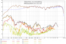 ainogice vx2 out distor.png143.6 KB · Views: 405
 -
 ainogice vx2 out 0 15 30 45 60 90¤ 20oms 13.png70 KB · Views: 522
 -
 ainogice vx21 out 0 +5 +10 +15 +225 +30¤ 20ms 112.png76.2 KB · Views: 390
 -
 ainogice vx21 out 0 -5 -10 -15 -225¤ 20ms 13.png66.3 KB · Views: 383
 -
 ainogice vx21 out spl phase 200ms 112.png66.1 KB · Views: 380
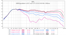
Rudolf was so nice to convert my measurements to ARTA for polar graphics. Here are version vX2 outdoor horizontal directivity in different ways.
I am trying to find the reason for the 2 -2,2kHz discontinuity. It must be some resonance or interference/reflection, but from where???
I am trying to find the reason for the 2 -2,2kHz discontinuity. It must be some resonance or interference/reflection, but from where???
Attachments
Perhaps instead of a 30° conical flare rate we should consider closer to 45° ?
Haven't come up with an alternative means to reduce this reflection. 🙁
Haven't come up with an alternative means to reduce this reflection. 🙁
I don't know why but it is nice to see that horizontal blooming at 2kHz is compensated by vertical dropout at same frequency! (see post #264) This area is clean in fardield room measurements.
I am trying to figure out the reason for this. Nearfiel (5cm) onaxis doesn't have this dip at 2.2, but it can be seen at 1m on-axis bot a single driver or both of mtm. Off-axis behaves just the same with 1 or 2 drivers. 1/4 wavelength of 2kHz is 4cm. Obviously the reflections comes from the driver's own spider/magnet or the nearby large magnet of NeoCD3.5
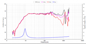
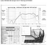
Here is NE95 in a standard IEC baffle (Peerless datasheet), we can see very similar variations! Perhaps this will remain as the "beauty mark" of AINOgradient! It is also good that it appears at a very limited range (high Q) and is compensated hor/vert.
Perhaps I should try some other 4" frame drivers... actually I have a pair of TangBand fullranges resting somewhere...
I am trying to figure out the reason for this. Nearfiel (5cm) onaxis doesn't have this dip at 2.2, but it can be seen at 1m on-axis bot a single driver or both of mtm. Off-axis behaves just the same with 1 or 2 drivers. 1/4 wavelength of 2kHz is 4cm. Obviously the reflections comes from the driver's own spider/magnet or the nearby large magnet of NeoCD3.5
Here is NE95 in a standard IEC baffle (Peerless datasheet), we can see very similar variations! Perhaps this will remain as the "beauty mark" of AINOgradient! It is also good that it appears at a very limited range (high Q) and is compensated hor/vert.
Perhaps I should try some other 4" frame drivers... actually I have a pair of TangBand fullranges resting somewhere...
Attachments
Last edited:
I was checking for alternative 4" mids/fullranges... Mark K has measured the Scanspeak 10F4424 extensively and John K uses it in Nao NoteII - and hopla! it is also peaking at 2,0kHz!
Siegfried L is using SEAS MU10 which doesn't have this peak, but instead peaks at 1,4kHz!

Siegfried L is using SEAS MU10 which doesn't have this peak, but instead peaks at 1,4kHz!
Attachments

Last edited:
I had a day off from work. It means tuning AINOs and cleaning the house!
I was working indoor. I took off the HM NE95 drivers and chamfered the openigs more. The plywood frame is 8mm thick, now it has been rounded more. I made some adjustments in the crossover too with indoor 1m measurements, concentrating only n range around 2kHz. Some improvement perhaps.
Thank you Greebster and Rudolf for your invaluable help!
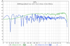
Response at 1m and at 2,5m different IR gate. 0¤ 30¤ 60¤ responses zoomed around 2kHz, no smoothing.
Today I have listened to these records while "working"
- Iiro Rantala - Lost Heroes
- Mariza - Concierto em Lisboa
- Joni Mitchell - Both Sides Now
- Marian Petrescu - Thrivin'
- Carpenters - Gold
- Eva Cassidy - Live at Blues Alley
I was working indoor. I took off the HM NE95 drivers and chamfered the openigs more. The plywood frame is 8mm thick, now it has been rounded more. I made some adjustments in the crossover too with indoor 1m measurements, concentrating only n range around 2kHz. Some improvement perhaps.
Thank you Greebster and Rudolf for your invaluable help!
Response at 1m and at 2,5m different IR gate. 0¤ 30¤ 60¤ responses zoomed around 2kHz, no smoothing.
Today I have listened to these records while "working"
- Iiro Rantala - Lost Heroes
- Mariza - Concierto em Lisboa
- Joni Mitchell - Both Sides Now
- Marian Petrescu - Thrivin'
- Carpenters - Gold
- Eva Cassidy - Live at Blues Alley
Attachments
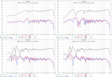
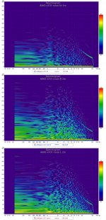
Rudolf Finke www.dipolplus.de has edited and analyzed my outdoor measurements and here is his statement of AINOgradient horizontal directivity, published with his permission!
Hello Juha,
There are about 30 different frequencies to choose from in the Arta directivity pattern tool. Obviously it does not make sense to use all of them in a single polar diagram - it would be too crowded. But if we separate them intelligently, they show the changes in a radiation pattern well. I tried to do that for the Aino.
In the uppermost diagram we see the radiation pattern changing with rising frequency from true omni to increasing directivity. The red 250 Hz line is already bordering on dipole pattern.
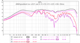
The diagram in the mid shows the fully developed dipole pattern from 315-1250 Hz.
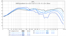
In the bottom diagram the radiation pattern widens from 1,6 to 2 kHz (which is the outermost line). But it is not dipole blooming (as happens in a too wide baffle), but the return of the pattern to monopole. Note how the 2 kHz line is almost identical with the red 250 Hz line in the upper diagrams. Beyond 2 kHz the radiating beam narrows continually as was to be expected.
I don't show the narrowing above 8 kHz - it is progressive.
Rudolf
www.dipolplus.de
Hello Juha,
There are about 30 different frequencies to choose from in the Arta directivity pattern tool. Obviously it does not make sense to use all of them in a single polar diagram - it would be too crowded. But if we separate them intelligently, they show the changes in a radiation pattern well. I tried to do that for the Aino.
In the uppermost diagram we see the radiation pattern changing with rising frequency from true omni to increasing directivity. The red 250 Hz line is already bordering on dipole pattern.
The diagram in the mid shows the fully developed dipole pattern from 315-1250 Hz.
In the bottom diagram the radiation pattern widens from 1,6 to 2 kHz (which is the outermost line). But it is not dipole blooming (as happens in a too wide baffle), but the return of the pattern to monopole. Note how the 2 kHz line is almost identical with the red 250 Hz line in the upper diagrams. Beyond 2 kHz the radiating beam narrows continually as was to be expected.
I don't show the narrowing above 8 kHz - it is progressive.
Rudolf
www.dipolplus.de
Attachments
One more notice about my measurements
in and outdoor show different pattern at 2-3kHZ, the dip at 2.1kHz seems typical to my outdoor measurements, done sharply at 150cm. Indoors the latest measurements have been done at 1m to minimize reflections.
Seems like using too little smoothing has lead me to pay attention to artefacts!
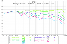
The last measurement v31 has a little too high level between 2-3kHz. I adjusted that by shaping Tweeter eq. So, it is now even smoother, very close to v2 indoors. v2has better directivity at 3kHz because of higher xo around 2900Hz. v31 has now 2300hz set at minidsp, to avoid mtm lobing.
in and outdoor show different pattern at 2-3kHZ, the dip at 2.1kHz seems typical to my outdoor measurements, done sharply at 150cm. Indoors the latest measurements have been done at 1m to minimize reflections.
Seems like using too little smoothing has lead me to pay attention to artefacts!
The last measurement v31 has a little too high level between 2-3kHz. I adjusted that by shaping Tweeter eq. So, it is now even smoother, very close to v2 indoors. v2has better directivity at 3kHz because of higher xo around 2900Hz. v31 has now 2300hz set at minidsp, to avoid mtm lobing.
Attachments
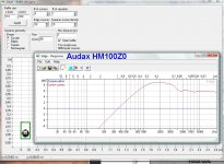
A candidate for a single highmid, replacing two NE95 drivers
Audax HM100Z0 Aerogel mid, price 76€, sensitivity 93dB. Look at response and csd!
Audax HM100Z0 Aerogel mid, price 76€, sensitivity 93dB. Look at response and csd!
Attachments
Oh boy, I found a pair of Audax HM100Z0 for a reasonable prize from a French webshop and placed an order! It will replace dual Peerless NE95s.
Plans of AINOgradient II
Edge simulation of a square framed 110mm wide Audax and a photomanipulation... Audax should be clean to almost 5kHz and with sensitivity of 93dB/W. A single unit can be crossed higher to tweeter, around 3500-4500Hz LR4 - then I stretch true dipole function 1kHz up and avoid mtm-typical lobing below xo. Vertical dispersion is not uniform, but "usual WMT". With dsp I can tilt summing axle (time-alignment) a bit upwards by adjusting delays.
Attachments
Last edited:
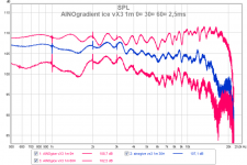
More room measurements to show how difficult it is to analyze room response.
At 1m 0¤ L speaker was in the middle of the room far from walls, I eq'd response straight at 15¤ angle. Then I pushed it back to normal place, ~80cm from wall, distance 2m to mic. L and R are not at exactly same angle and distance. I should do a nearfield measurement to check the tweeter of R. In graphics I lifted 1m response 10dB higher for better visualization.
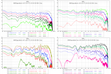
Same three measurement sweep with REW, just different IR gating. We notice how each gate picks different room reflections to the graph. It is difficult to make conclusions! Decay spectrums of each measurement too.
Directivity at same 1m distance indoors (I eq'd the 15¤ response maximally first)
At 1m 0¤ L speaker was in the middle of the room far from walls, I eq'd response straight at 15¤ angle. Then I pushed it back to normal place, ~80cm from wall, distance 2m to mic. L and R are not at exactly same angle and distance. I should do a nearfield measurement to check the tweeter of R. In graphics I lifted 1m response 10dB higher for better visualization.
Same three measurement sweep with REW, just different IR gating. We notice how each gate picks different room reflections to the graph. It is difficult to make conclusions! Decay spectrums of each measurement too.
Directivity at same 1m distance indoors (I eq'd the 15¤ response maximally first)
Attachments
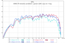
The right tweeter problem solved! It was the protective capasitor connected to + leg on the R. Here are measurements of R false and fixed and L.
I have used the L speaker for my tests. The mirrored connection was done by purpose because of making a visually mirrored pair... Now the cap on the right shines to my eyes when I angulate speakers 🙁
I have used the L speaker for my tests. The mirrored connection was done by purpose because of making a visually mirrored pair... Now the cap on the right shines to my eyes when I angulate speakers 🙁
Attachments
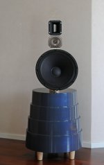
Better photos of the finished AINOgradient!
What an awesome project! I heard the Gradient Helsinki this year and it blew me away. I'm messing with some Beolab5-type speakers, and the radiation pattern and goals is similar to what Gradient is doing. (radial radiation, wire directivity horizontally with narrow directivity vertically, a speaker that's less room dependent, waveguides, etc.)
Thanks Patrick! I admire your enthusiasm and creativity with Beolab clone among other projects! I haven't heard Helsinki but sure I have studied it too. Seems like (based on stereophile measurements) that it doen't have as much directivity as my 1.3 clone, but is extremely smooth in that. A Finnish friend of mine has launched a project of cloning G. Helsinki.
We Finns have a long history with directivity control, dipoles and waveguides, Jorma Salmi and many others have studied it a lot and published many articles in journals, starting in 1980's
We Finns have a long history with directivity control, dipoles and waveguides, Jorma Salmi and many others have studied it a lot and published many articles in journals, starting in 1980's
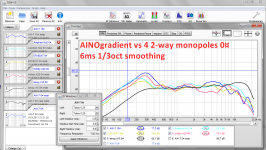
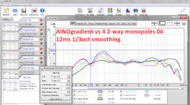
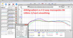
Comparison of AINOgradient to 4 2-way monopoles
AINOgradient is cardioid from 80 to 200Hz, dipole 22-2kHz and monopole up there. The fundamental notes of solo instruments and voice are mostly at 40-1000Hz and most annoying room reflections appear at those frequencies. Cardioid and dipolic radiation reduces reflections from sidewalls and high vertical directivity from floor/ceiling.
Measurements were done at same setup, the speaker on a stand in the middle of the room. There is some bounces that can be seen in the first picture, when compared to nearfield 15cm.
AINOgradient has a very different behaviour in these measurements. However, when paced in the normal listening position, even AINO suffers from floor bounce, but less that a 2-way monitor on a stand. I have shown this difference in an earlier post. Having the speaker at 30-45¤ angle to the front wall greatly reduces early and strong front-wall reflections
Attachments


- Home
- Loudspeakers
- Multi-Way
- Aino gradient - a collaborative speaker project