What exactly does that R9/R10/C5 combination exactly do? Shouldn't C5 be paralleled with R9 and R10 be directly connected to the supply voltage?
Best regards!
Best regards!
This is a ripple null circuit. Its a very old idea. I read it in the Langford Smith book making further reference to an aticle from Wen-Yan Pan in the Preccedings IRE September 1942.What exactly does that R9/R10/C5 combination exactly do? Shouldn't C5 be paralleled with R9 and R10 be directly connected to the supply voltage?
Best regards!
Basically the voltage divider must have the same value of "gain" as the tubes. And the capacitor must have low reactance at some desired low frequency cutoff. I believe 1Hz is reasonable. Some authors add a phase compensation for the divider.
Originally the circuit used the screen or suppressor of a pentode to perform the same action.
Originally the circuit used the screen or suppressor of a pentode to perform the same action.
In case it hasn't been mentioned before, try some freeze spray on the passive components. This might reveal the culprit!
In tube circuits with high voltages ot is a bit dangerous. Not only it condensates humidity, it can break a tube or any other hot part.
Note the words "passive components". I would assume someone has enough sense to not drown the board and tubes with freeze spray. A little goes a long way to indicate a problem -passive- component. We are also not talking about 2kv+ voltages here.In tube circuits with high voltages ot is a bit dangerous. Not only it condensates humidity, it can break a tube or any other hot part.
What is the purpose of R12 on the B+ line here?
Would you know what values are used for R3/R4? - I have 1K on mine, running 5mA through that valve.
Well folks,
I checked all the resistors today, measured each one, and each one matches the BoM - I was hoping to find something wrong to be honest, but it wasn't to be. I also tried increasing and reducing the current through each set of valves by altering the cathode resistors. At this stage I am tapped out of ideas to try.
I checked all the resistors today, measured each one, and each one matches the BoM - I was hoping to find something wrong to be honest, but it wasn't to be. I also tried increasing and reducing the current through each set of valves by altering the cathode resistors. At this stage I am tapped out of ideas to try.
You tried them all, but nothing better happened. At this point, I would try to remove the capacitor from the positive to the right low grid on both channels. Next step you can try to remove the tubes from one channel and observe; if unsuccessful, try to remove the tubes from the other channel. You can also try with the only right tube installed (if you have the divider polarizing the right high grid). The last chance is to remove the PCB from the cabinet (it is a good occasion to check if some dirt accumulated on some tracks) and try again. In one way or another, you will resolve the "pop", I'm confident you will. But resolving the slow oscillation you see on the scope is another thing, which I was able to resolve only with a Virtual Battery.
So I took the decision to try rule out everything I could. I removed every resistor and cap form the board, cleaned the whole thing down with solvent, then baked it at 100degC for 45mins just in case there was anything causing leakage etc of some kind. I then checked every resistor and replaced them all, 300R cathode resistors all round (8mA per triode) and 470R carbon film grid stoppers. This produced no change in the slow oscillation.
I found an old thread here where another guy had slow motorboating with a 6SN7 aikido. The thread didn't resolve, but I found another thread where he said he used a regulated supply and that solved it. So I pulled an old Maida reg I had and fitted that. This seemed to make it better alright, but I still had the slow oscillation albeit at a lower level. Quite a bit of advice in that thread was not to use a choke, so I removed the choke I had there (10H, 500R) and replaced it with a 470R resistor. Supply was now CRCRC. This also made no difference, although I felt I might have been making a move in the right direction as the size of the oscillation had gotten smaller. I then added some more capacitance on the aikido board itself - 180uF. This really seemed to help, so now I had CRCRC then maida, then local decoupling on the board. Unfortunately while the oscillation is lower, it still triggers the DC protect in the power amp.
I suppose the only thing left is the virtual battery as suggested by @marigno - I take it you mean a capacitance multiplier? I don't know if I am going to go to those lengths and I think at this point I might just shelve this one. Maybe I'll be inspired in a few days or something...... Maybe I'll go put a different circuit together in the same box instead.
My first Aikido is with the Virtual Battery, you find an example of it in my WOTS link, you only have to take into account the increased voltage and choose suitable parts. Another good one is the PS21 I used in my second Aikido, 275Vac input, and 250Vdc output. No oscillation with any of them. I would prefer the Virtual Battery because it has no feedback. But you have to design the PCB, mine handles 150V output and is not suitable for your voltage (should be almost 400Vdc after rectifiers). JLCPCB is a good and cheap service to obtain good quality PCBs. I always choose a transformer with Vac (sec)>=Vdc (obtained). Do not give up!!!
So I took the decision to try rule out everything I could. I removed every resistor and cap form the board, cleaned the whole thing down with solvent, then baked it at 100degC for 45mins just in case there was anything causing leakage etc of some kind. I then checked every resistor and replaced them all, 300R cathode resistors all round (8mA per triode) and 470R carbon film grid stoppers. This produced no change in the slow oscillation.
I found an old thread here where another guy had slow motorboating with a 6SN7 aikido. The thread didn't resolve, but I found another thread where he said he used a regulated supply and that solved it. So I pulled an old Maida reg I had and fitted that. This seemed to make it better alright, but I still had the slow oscillation albeit at a lower level. Quite a bit of advice in that thread was not to use a choke, so I removed the choke I had there (10H, 500R) and replaced it with a 470R resistor. Supply was now CRCRC. This also made no difference, although I felt I might have been making a move in the right direction as the size of the oscillation had gotten smaller. I then added some more capacitance on the aikido board itself - 180uF. This really seemed to help, so now I had CRCRC then maida, then local decoupling on the board. Unfortunately while the oscillation is lower, it still triggers the DC protect in the power amp.
I suppose the only thing left is the virtual battery as suggested by @marigno - I take it you mean a capacitance multiplier? I don't know if I am going to go to those lengths and I think at this point I might just shelve this one. Maybe I'll be inspired in a few days or something...... Maybe I'll go put a different circuit together in the same box instead.
Did you ever resolve the oscillation with your Aikido?
I'm seeing the same issue with one I just assembled - using Broskie's rev. F octal board and PS-21B power supply. Fluctuating DC offset on the output that will randomly spike up past 100mV. I also get pops/scratchiness in between steps on the Goldpoint attenuator I'm using.
I'm wondering if there's an issue with this new PCB revision? Tried contacting Broskie and no response.
It's the power supply, not the audio circuit. The low frequency oscillation is caused by the supply time constants.
The audio circuit is direct coupled, and amplifies DC, as far as the supply is concerned.
Add decoupling between the second and first stages.
The audio circuit is direct coupled, and amplifies DC, as far as the supply is concerned.
Add decoupling between the second and first stages.
Well, noticed that my heater elevation was way off - close to 180V when it should be 60V. Traced out the PCB and found that R13 + R14 (voltage dividers for heater elevation) are mislabeled on the board. Going to swap those resistors and see if that solves it.
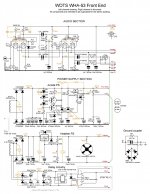
I have an update to the Virtual Battery, it regards a better CCS (the one with the depletion mosfet does not work), now in cascode with very high impedance, to better insulate the gate from the noise after rectification. I have the whole WHA-53 front-end scheme, just look only at the anode power supply. Rock solid voltage without feedback. The PS-21 too is a good stabilizer, but it works with feedback.
Attachments
- Home
- Amplifiers
- Tubes / Valves
- Aikido octal pops/dc